Connecting to the auxiliary I/O interface 45
Connecting a 2-wire proximity sensor to an auxiliary input signal
You can connect a 2-wire proximity sensor to a Matrox Iris GTX auxiliary input
signal in either a sourcing or sinking configuration (that is, on a positive or negative
power wire). Note that in both cases, you will need to install an external bleeder
resistor, to ensure that a minimum amount of current flows into the proximity
sensor in its on-state and in its off-state.
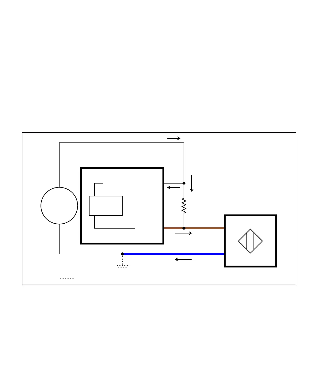
• For the auxiliary input signal to source the current (that is, to connect an auxiliary
input signal on a positive power wire), connect the 2-wire device to the auxiliary
input signal as shown below. You must also install an external bleeder resistor
between the AUX_IN_COMMON pin and brown wire of the proximity sensor.
The bleeder resistor’s value should guarantee that the minimal required current is
provided to the connected sensor (the third-party device). For details regarding
the sensor’s minimum current requirements, refer to its documentation. Note that
you should use a bleeder resistor with an appropriate power rating for your circuit.
Equivalent circuit only
Brown wire
Blue wire
2-wire NPN
proximity sensor
24V
Sensing
Circuit
AUX IN_
AUX IN_COMMON_
Matrox Iris GTX
Sourcing configuration
+
-
Optional because the auxiliary input signals are optically isolated.