14 Chapter 2
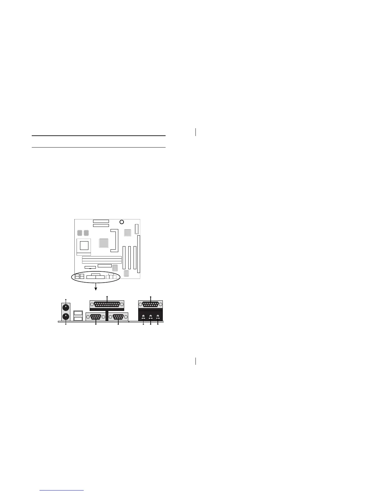
Connectors
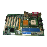
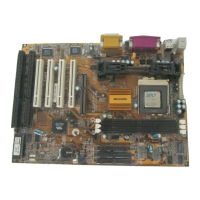
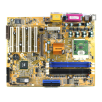
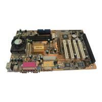
Attach system components and case devices to the
mainboard via the mainboard connectors. A description of
each connector follows. See Figure 2–1 for the location of
the connectors on the mainboard.
Note:Make sure that the power is turned off before making
any connection to the board.
FDC1 – Floppy Disk Drive Port
IDE1/IDE2 – Primary/Secondary IDE Ports
COM2 - Serial Port 2
Side View
Game (15-pin Female)
Line-In/Rear
MIC
Line-Out
PS/2 Mouse (6-pin Female)
Parallel (printer) port (25-pin Female)
PS/2 Keyboard (6-pin Female)
COM1 VGA1
Serial Port 1 VGA Connector
USB
Chipset
Sound
I/O Chip
Chipset
Cache
Cache




 To Next Page