Chapter 2
16
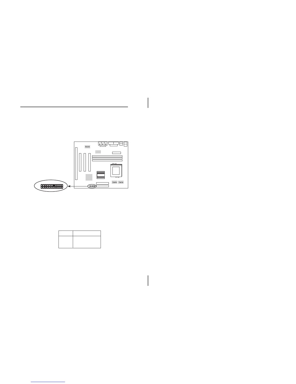
The case connectors contain: Speaker, Power LED,
Keylock, Turbo LED, HDD LED, Reset Switch, and Power
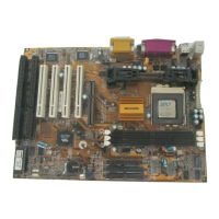
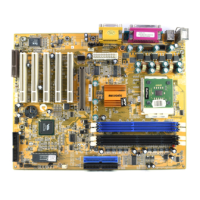
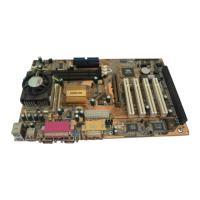
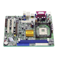
Button. Refer to the following drawing for the location on
the mainboard.
pin1, 3, 5, 7 – Speaker
pin2, 4, 6 – Power LED
pin8, 10 – Keylock
pin13, 14 – Turbo LED
pin15, 16 – HDD LED
pin17, 18 – Reset Switch
pin21, 22 – Power Button
1
2
21
22
J9
Chipset
Chipset
I/O
1
2
21
22
J9
Case Connectors: J9
J9 (21, 22) - Power Botton/Suspend Switch
Connector
Refer to the ATX Functions & Connectors section.
J9 (17, 18) - Reset Switch Connector
Normal Mode
Reset System
Open
Close
Setting Description




 To Next Page