i-MAX Industrial inverter air/water heat pump with axial fans
17
outlet water sensor exceeds r02+r06 in heating mode or r03+r06 in cooling mode and in shut off condition (the default value is
r06=2,0°C). The heating cable placed on the basement of the appliance turns on when the outdoor air temperature decreases
below 3°C and the unit starts the defrosting cycle (or if r19=0 even if the unit is not in defrosting cycle, or in stand-by mode). It will
be deactivated if the outdoor temperature exceeds 5°C or the last defrosting cycle is concluded after more than r19 minutes
(default 10 minutes) (with r19≠0).
If you want to produce gelid water, it is necessary to modify the actions of antifreeze resistances, as well as the set of activation of
the antifreeze alarm (A08 = 4°C by default) and its hysteresis (A09 = 3.0°C by default).
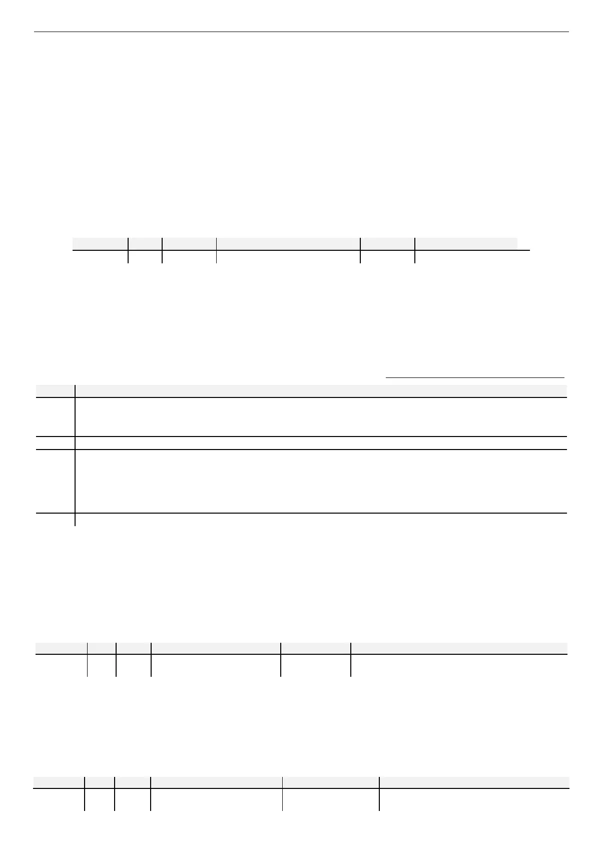
7.9 Remote ON/OFF
The ON/OFF function is already enabled by default. Remove the bridge of the terminal block then the unit will be placed in stand-
by mode (in such status the display of the on-board unit controller will show the "E00" code). When the contact is closed, the
appliance exits from standby mode and the circulation pump will be activated for 2 minutes.
To change this function, enter at the parameters PRGPSSPRG(introduce the maintainer password)PRGPArPRGCnF
See paragraph 11.2.
Note: In the case of a remote switch Off during the defrost cycle, the unit will terminate this process before stopping completely
the cooperation.
Remote On/Off digital input
Non-voltage digital input
If the domestic hot water is enabled and the parameter “H10” is configured as below:
− If H10 = 1/3/5, the remote on-off function has no any effect on sanitary operation; it only disenables the heating and
cooling on the plant system side (in such case the "SAN" item will be shown on the display of the on-board unit controller).
− If H10 = 2/4/6, the remote on-off function disenables the production of domestic hot water and the operation of the heat
pump in heating and cooling mode on plant circuit side.
8 ACTIVABLE SIGNALIZATIONS FOR 0466, 0475 AND 0485 SIZES
As for the sizes indicated above, on the DO3 – DO3N terminals (Parameter H81), it’s possible to configure a 230Vac signal output
voltage by setting the following user parameters introducing the installer password in the control panel located on the front panel.
21
Signalization of defrosting period
• The digital output is activated at the beginning of defrosting cycle, once the Pa d06 time period has terminated.
•
The digital output is deactivated at the end of defrosting cycle, once the Pa d07 time period is terminated.
Signalization of heat pump alarm
31
Signalization of plant season.
• The output is active in COOLING operation
• The output is not active in heating operation
• The output is not active when the unit s OFF.
During the DHW production and defrosting cycle, the output keeps the settings of the provenance season.
Signalization of appliance lockout
9 ACTIVABLE LOGIC FUNCTIONS WITH GI- MODULE FOR PLANT MANAGEMENT (optional)
The following functions can be activated by the on-board controller which is located on the front panel of the unit.
9.1 DEFROSTING CYCLE SIGNALIZATION
It is possible to configure a digital output for the signalization of the beginning of defrosting cycle.
To enable this function, you should enter at the page of parameters PRGPSS PRG(enter the maintainer password)
PRGPAr PRGCnF.
See paragraph 11.2.
H86 num 21
Undervoltage output for defrost
cycle warning
DO1E(phase)
DO1E N(neutral)
Under-voltage output 230V ac, 50Hz, 5A resistive, 1A inductive.
Should be connected to the relay coil in order to get a free contact.
9.2 PLANT SEASON SIGNALIZATION
It is possible to configure a digital output for the signalization of the plant season mode of the unit.
The output is ON during summer mode operation, however is OFF when the unit is not operating or in winter mode.
The output keeps the configuration of last season operating mode during the DHW production or defrosting cycle.
To enable this function, you should enter at the page of the parameters PRGPSSPRG(introduce the maintainer
password)PRGPArPRGCnF.
See paragraph 11.2.
H87 num 31
Under-voltage output for plant
season signalization
DO2E(phase)
DO2E N(neutral)
Under voltage output single phase 230Vac, 50Hz, 2A (AC1),
for connection to the relay coil for obtaining a free contact.