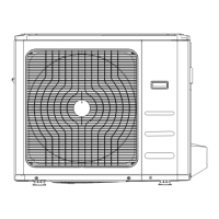
i-MAX Industrial inverter air/water heat pump with axial fans
29
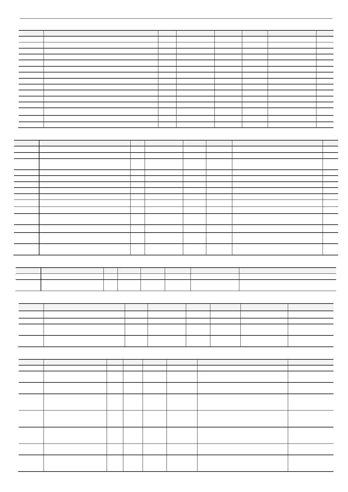
11.5 CONDENSATION PARAMETERS
Operation under compressor call
Max silent fan speed in cooling mode
Set of the pressure at the minimum speed of the fan in cooling
Proportional band for modulation of the fan in cooling mode
Delta cut-off fan adjustment
Max fan speed in cooling mode
Set of the pressure at the maximum fan speed in cooling
Max. silent fan speed in heating mode
Set of the pressure at the minimum fan speed in heating
Linear band for fan motor modulation in heating mode
Max. fan speed in heating mode
Set of the pressure at the maximum fan speed in heating
11.6 CIRCULATOR PUMP CONFIGURATION PARAMETERS
Pump ON Compressor ON delay
Pump OFF compressor OFF delay
P03 Pump operation mode / 1 0÷1 INSTALLER
0 = continuous operation
1 = operation according to the thermoregulation
Set of the pump in antifreeze
Hysteresis for the pump in antifreeze mode
Pump proportional band in heating
Maximum speed of modulating pump
Minimum speed of modulating pump
Set ΔT [°C] T
water inlet/outlet
of modulating pump
P16
Time between 2 activations of the pump in
periodic mode
min 20 0÷600 INSTALLER
Time of operation of the pump in periodic mode sec 90 0÷255 INSTALLER
0 = deactivation of periodic mode
P18 Enabling of unique pump operation in network / 0 0÷1 INSTALLER
0 = deactivated function
1 = enabled function
P19
Unique pump operation in network in presence
of offline machines
/ 0 0÷1 INSTALLER
11.7 DEFROSTING PARAMETERS
Pressure during initial defrosting
Parameters enabled only if are configured by default
d08
Minimum interval between 2
consecutive defrosting cycles
min 0 0÷255 INSTALLER
After a time equal to d08, the circuit enters in
defrosting mode.
11.8 COMPRESSOR CONFIGURATION PARAMETERS
Parameter Description Unit Default Range Visibility Allowed configurations Note
Output power from PC1 % Based on the model 0÷100 INSTALLER
n06 Compressors Lock Mode for installer / Based on the model 0÷1 INSTALLER
0 = Operation
1 = Lockout
C11
Operation time of compressor with
minimum frequency
sec 60 0÷255 INSTALLER
11.9 CONFIGURATION PARAMETERS OF “GI” Module – PLANT MANAGEMENT – (Optional)
H28
Configuration of the digital input
ST6E
/ 0 0÷49 INSTALLER
0 = input not assigned
6 = DHW temp. remote sensor
ST6E, ST6E terminals
H29
Configuration of the digital input
ST7E
/ 0 0÷49 INSTALLER
0 = input not assigned
41= Plant water temp. remote sensor
ST7E, ST7E terminals
H86
Configuration of the digital
output DO1E
/ 0 0÷47 INSTALLER
21= Defrosting warning
D01E, D01EN terminals
H87
Configuration of the digital
output DO2E
/ 0 0÷47 INSTALLER
31= Plant season warning
D02E, D02EN terminals
H88
Configuration of the digital
output DO3E
/ 0 0÷47 INSTALLER
22=Plant auxiliary electric heater
D03E, D03EN terminals
H89
Configuration of the digital
output DO4E
/ 0 0÷47 INSTALLER
0 = output not assigned
6= Sanitary valve
D04E, D04EN terminals
H90
Configuration of the digital
output DO5E
/ 0 0÷47 INSTALLER
26 = Double set point valve
43 = Secondary circulator
D05E, D05EN terminals