CONTROL ELEMENTS 4 - 1
DSE-17www.maxcess.eu MI 1064 1 C
Bedienelemente.fm
4 CONTROL ELEMENTS
Control elements
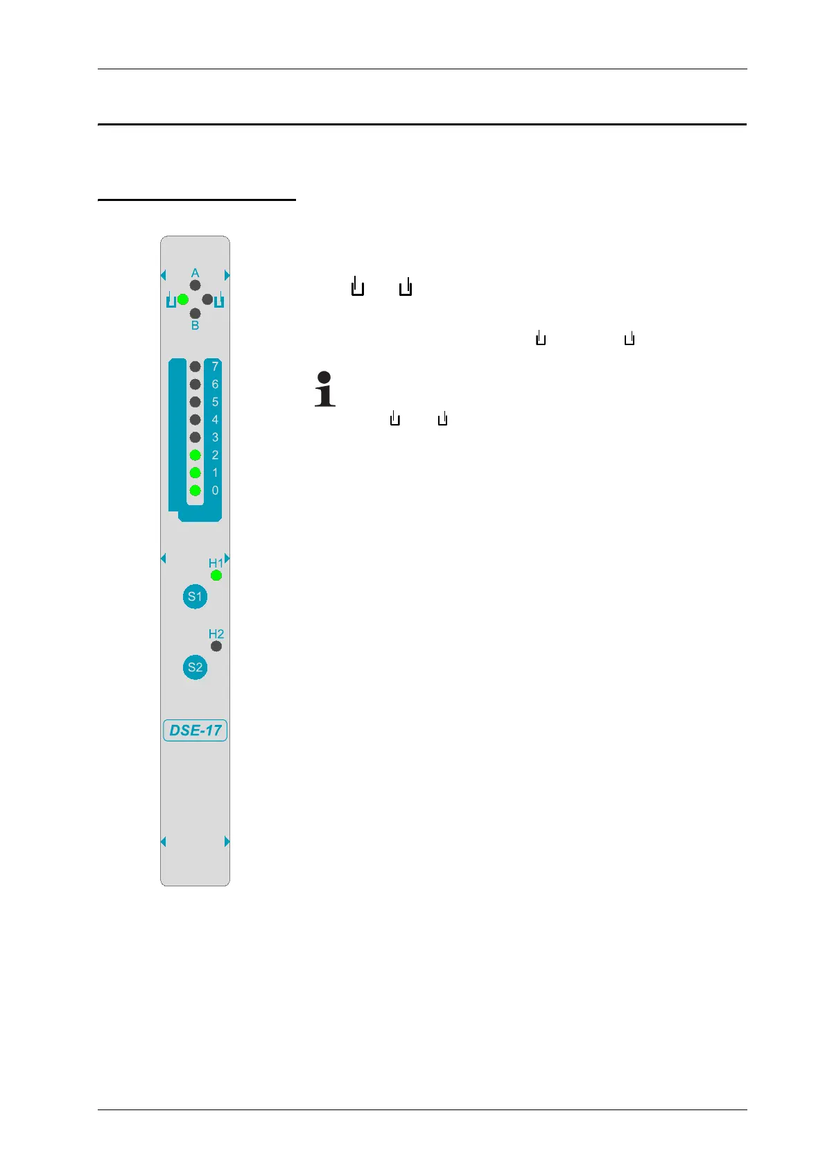
The DSE-17 sensor has the following control and display
elements.
LEDs and :
– The LEDs identify the position of the material that is being
tracked in terms of the upper and lower sensor sides.
Note:
When the material web is in the center of the sensor fork,
LEDs and are not lit.
LEDs A and B:
– Not assigned in its regular operation state
LED bar graph:
– Shows the tracked edges of the material web when the sensor
is working in the regular operation state.
S1 key:
– Generate auxiliary signals for calibrating the connected web
guide controller
S2 key:
– Perform calibration of the sensor
LED H1:
– LED H1 is continuously lit when the sensor is turned on and
working in its regular operation state.
– LED H1 flashes while it is generating auxiliary signals for
calibrating the connected web guide controller.
LED H2:
– LED H2 is turned off in its regular operation state.
– LED H2 flashes while the sensor is being calibrated.
– LED H2 flashes in a certain pattern. The sensor is indicating
an error.
table, page 8-1