TECHNICAL DATA9 - 4
DSE-17 www.maxcess.euMI 1064 1 C
Electrical connection Power supply
+10V - +28V
Output signal (depends on configuration)
0 - 10mA to ≤ 400Ω
0 - 20mA to ≤ 200Ω
4 - 20mA to ≤ 200Ω
Power consumption
Extension cable
Up to 15m (standard)
Up to 40m (optional)
X1 plug connector Normally the sensor must be connected to the web guide
controller with a cable on the corresponding sensor input. In
some cases the sensor can be connected via a Y-cable or an
external distributor box to two sensor inputs on the web guide
controller.
Use of individual analog signals is configuration-dependent.
For information regarding the specific configuration of this
sensor, refer to the drawing under the configuration number in
the system documentation.
Operating voltage Configuration
Maximum power
consumption
12V
4 x 20mA 150mA
4 x 10mA 130mA
24V
4 x 20mA 75mA
4 x 10mA 65mA
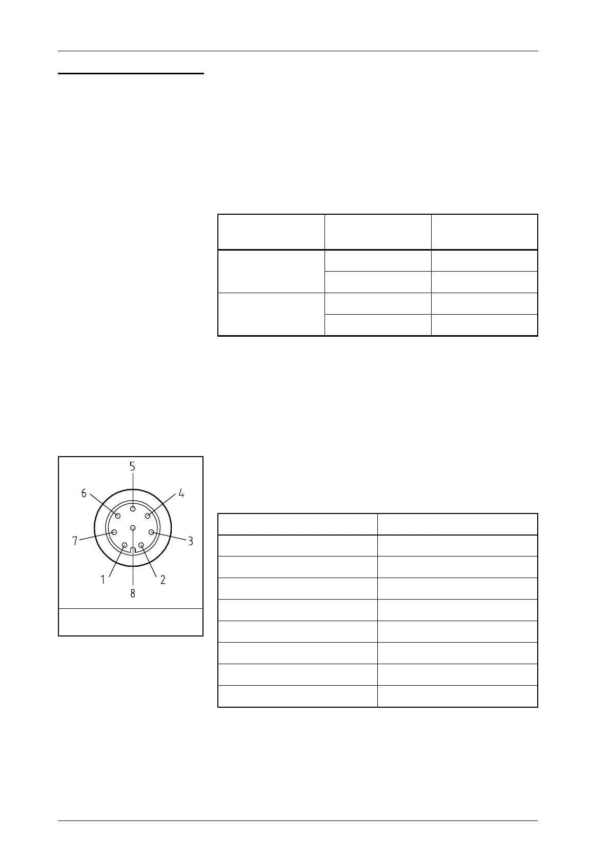
Pin on connection cable Function
1VCC (+12V)
2 Signal 2
3GND
4 Signal 1
5 RS485-B
6 RS485-A
7 Signal 3
8 Signal 4
Figure 9.2: M12 connector as seen
from the connection side