Motherboard Design Guide
Requirements for Components of Third-party Suppliers
maxon motor control
EPOS4 Positioning Controller Document ID: rel8003
4-73
EPOS4 Module/Compact 50/5 Hardware Reference Edition: May 2018
© 2018 maxon motor. Subject to change without prior notice.
4.1.3 Logic Supply Voltage
The Module features a logic supply voltage input. Its voltage range is 10…50 V and must be either
sourced separately or by the power supply voltage.
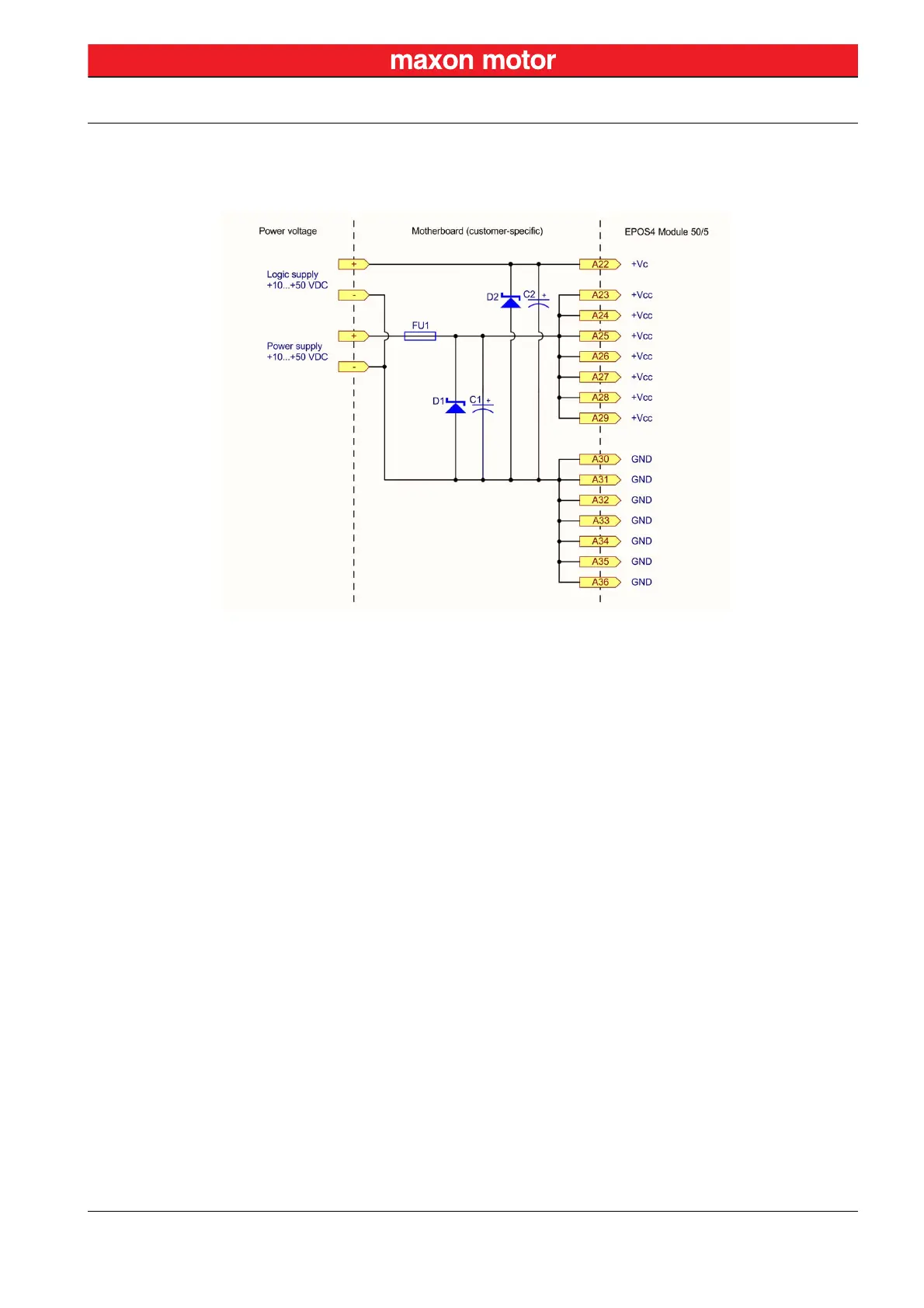
Figure 4-49 Wiring of logic supply
TVS D
IODE (D2)
If the logic supply voltage is sourced separately, a transient voltage suppressor diode (D2) at the logic
supply voltage input can be connected to protect the module against overvoltage.
C
APACITOR (C2)
Use an electrolytic capacitor (C2) if the logic supply is sourced separately. This will avoid oscillations
caused by supply cable inductance or the Module’s built-in capacitors that could lead to a voltage over-
shoot at power plug-in.


 To Next Page