11921 Slauson Ave. Santa Fe Springs, CA. 90670 (800) 227-4116 FAX (888) 771-7713
37
PLATFORM WILL NOT LOWER, LOWERS TOO SLOWLY OR TOO QUICKLY
CAUTION
Keep dirt, water and other contaminants from entering the hydraulic system. Before
opening the hydraulic fl uid reservoir fi ller cap, drain plug and hydraulic lines, clean up
contaminants that can get in the openings. Also, protect the openings from accidental
contamination during maintenance.
NOTE: In most cases, you can avoid having to bleed the hydraulic system by
correctly positioning Liftgate platform before opening hydraulic lines. Refer to
following procedure. Save time on the job and prevent accidental fl uid spills and
hazards.
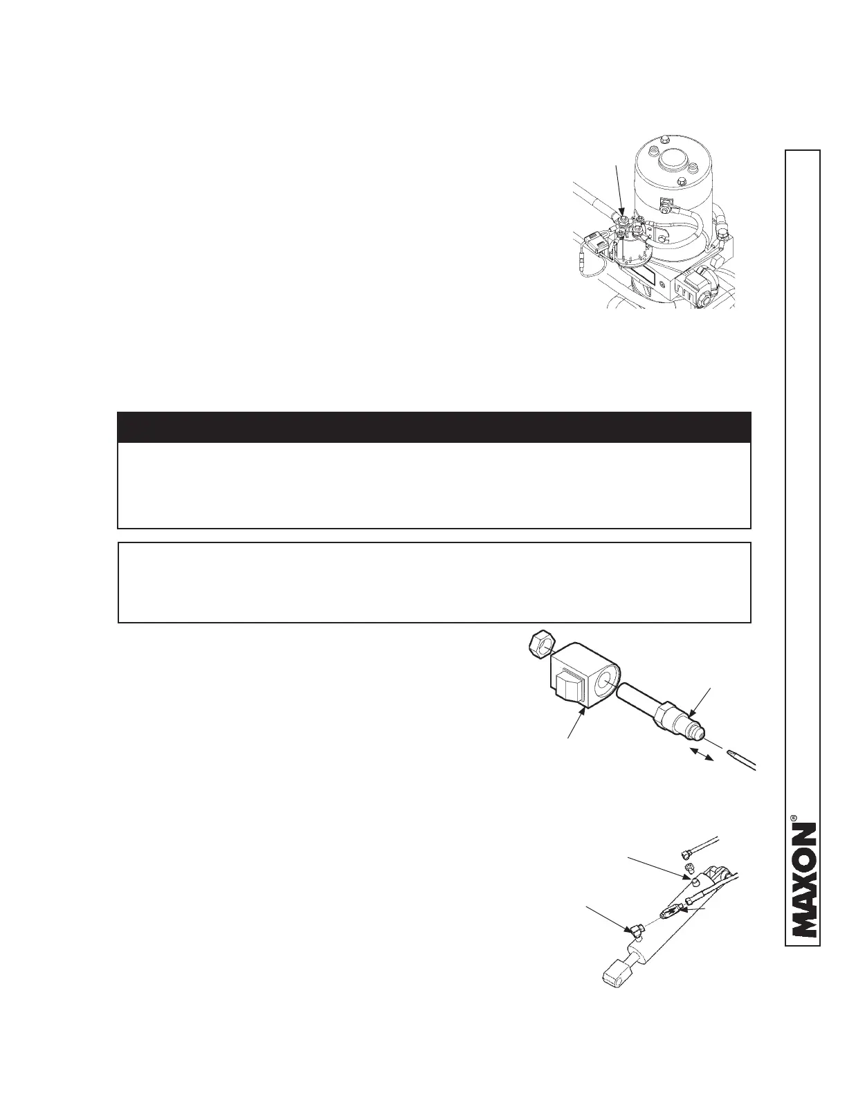
1. Use voltmeter to verify power is being supplied to
solenoid terminal “B”. Recharge the battery if volt-
meter displays less than 12.6 volts (FIG. 37-1).
2. Check for structural damage or poor lubrication.
Replace worn parts.
3. Check if solenoid valve is getting power by holding a
screwdriver against the top nut of the solenoid. Push
control switch to “lower” position to energize solenoid
(FIG. 37-2). A good solenoid will attract (magnetically)
the screwdriver to the nut and make it diffi cult to pull
the screwdriver away from the nut.
4. Check the valve stem by removing the coil assem-
bly (Item 1, FIG. 37-2). With platform supported,
unscrew the valve stem (Item 2, FIG. 37-2) from
the pump. Push on the plunger located inside the
valve stem by inserting a small screwdriver blade in
the end. If the plunger does not move freely (approxi-
mately 1/8”), replace the valve stem.
6. Check and clean fl ow control valve in high
pressure hydraulic line attached to cylinder.
5. Check if fi ltering screen on solenoid valve is
plugged. Clean carefully if required.
2
1/8”
1
FIG. 37-2
FLOW
CONTROL
VALVE
VENT/DOWN PORT
(REF)
RAISE PORT
(REF)
FIG. 37-3
7. Check if fl ow control valve (FIG. 37-3) is
pointing to the direction of restricted fl uid
fl ow (back toward pump). If required, remove
fl ow control valve and install it correctly (FIG.
37-3).
TERMINAL “B”
BATTERY (+)
FIG. 37-1

 Loading...