1.9 Operation of position control mode with simple wiring
Wiring
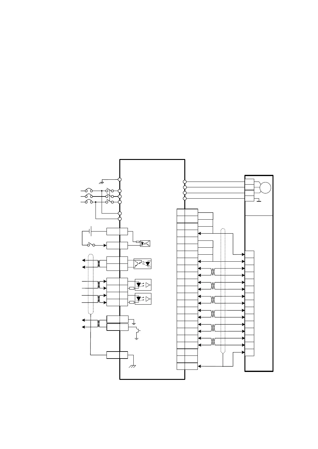
According to the picture 7.8 make the wiring carefully.
z The main circuit terminal R、S and T connect with three phase AC 220V power supply.
z The terminal ‘r’ and‘t’ of control power supply connect with single phase AC 220V power
supply.
z The output terminals(U,V,W) must be connected with the servo motor connections(U,V,W)
correspondently, otherwise the servo motor will stop or over speed.
z Using the encoder connector CN2 connect the servo driver with the servomotor.
z Using the control signal connector CN1 connect other wiring according to the drawing.
3 Phase
AC220V
NFB
MC
R
S
T
r
t
DC
12~24V
Servo ON(Enabled)
Servo Ready
Position Command
PULSE
FG 36
CN1
CN2
EP100(B) SERVO DRIVER
SERVOMOTOR
PE
4.7k
26LS32
Receiver
Ground of
Metal Case
SRDY+ 8
SRDY- 25
COM+ 18
SON 10
Maxsine
U
V
W
PE
4 Pins Connector
For Motor Power
PULS+ 32
PULS- 33
220
SIGN+ 34
SIGN- 35
220
14 5V
15 5V
16 5V
17 5V
18 0V
19 0V
20 0V
21 0V
1 A+
2 A-
3 B+
4 B-
5 Z+
6 Z-
7 U+
8 U-
9 V+
10 V-
11 W+
12 W-
22 0V
23 0V
26 FG
2
3
4
1
3
4
7
5
8
6
9
10
13
11
14
12
15
1
2
7
CZ
9GND
Z Signal of Encoder
(OC Output)
Ground of
Encoder Signal
Z
GND
15 Pins Connector
For Optical Encoder
Position Command
SIGN
Optical Encoder
Motor
Picture 9.0 Simple wiring diagram of position control mode