1.2 Terminal disposition for interface
Figure 3.1 is the disposition chart of terminal connector CN1 for the servo driver. CN1 is
the connector with 36 cores. Figure 3.2 is the disposition chart of terminal connector CN2 for
the servo driver. CN2 is the connector with 26 cores.
79
810
11
12
13
14
15
16
17
18 6
1921
2426
23
28
25
30
27
32
29
34
31
5
22
3
20
1
4
2
3335
36
Figure 2.1 the soldering lug of the CN1 plug(face to lug)
13
24
5
6
7
8
9
10
11
12
13
1416
1517
18
19
20
21
22
23
24
25
26
Figure 2.2 the soldering lug of the CN2 plug(face to lug)
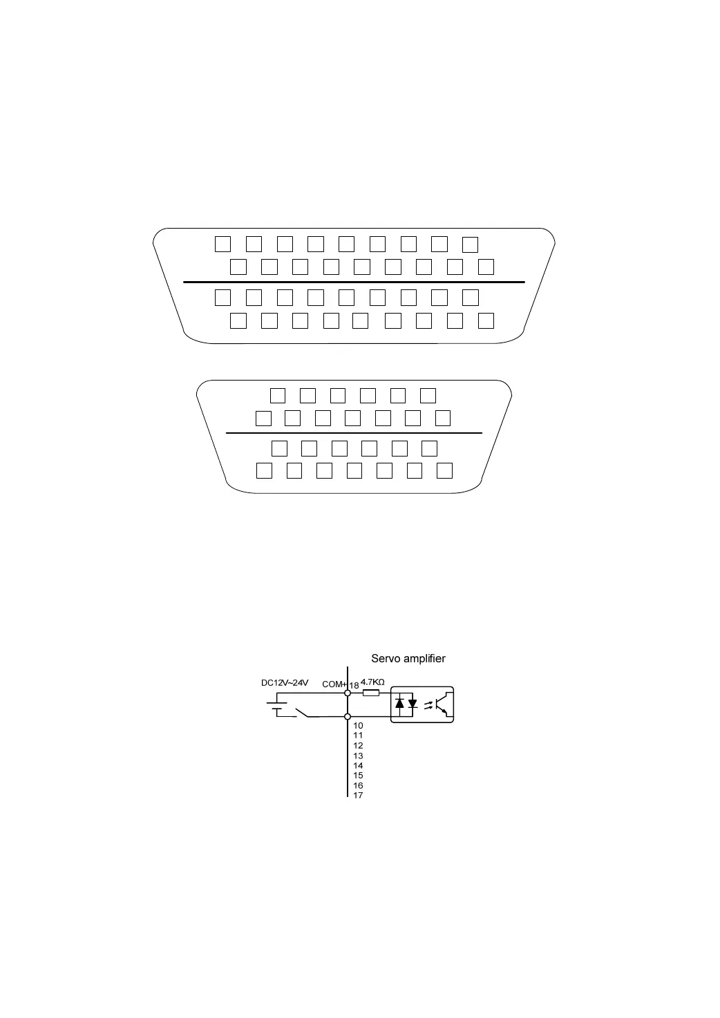
1.3 Input/output interface type
1.3.1 Switch value input interfaces
z The range of external DC power supply is 12~24V, and the minimum input current is
100mA .
z Inverting the polarity of DC power source, which is provided by the user, can cause the servo
driver damage.