9XTend‐PKG‐R™RS‐232/485RFModem–ProductManualv1.2.4
2.3. RS-485 (4-wire) & RS-422 Operation
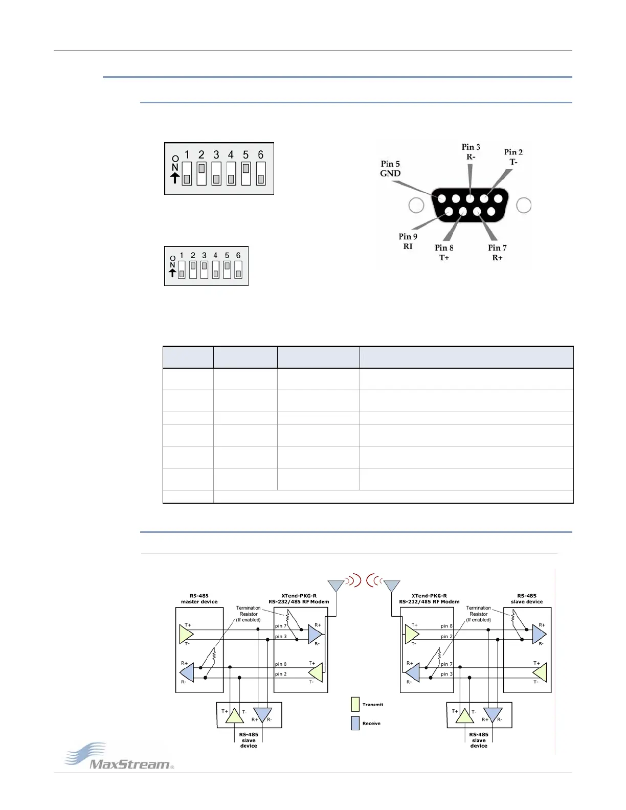
2.3.1. DIP Switch Settings & Pin Signals
Figure2.10.Figure2.11.
RS‐485(4‐wire)andRS‐422PinsusedonthefemaleRS‐232(DB‐9)
DIPSwitchSettingsSerialConnector
Figure2.12.
RS‐485(4‐wire)&RS‐422withTermination(optional)
Terminationisthe120ΩresistorbetweenT+andT‐
.
DIPSwitchsettingsarereadandappliedonlywhilepowering‐on.
Table2‐03. RS‐485/422(4‐wire)Signalsandtheirimplementationswith theXTend‐PKG‐RRFModem
DB-9 Pin
RS-485/422
Name
Description Implementation
2 T- (TA)
Transmit Negative
Data Line
Serial data sent from the XTend RF Modem
3 R- (RA)
Receive Negative
Data Line
Serial data received by the XTend RF Modem
5 GND Signal Ground Ground
7 R+ (RB)
Receive Positive
Data Line
Serial data received by the XTend RF Modem
8 T+ (TB)
Transmit Positive
Data Line
Serial data sent from the XTend RF Modem
9 PWR Power
Optional power input that is connected internally
to the front power connector
1, 4, 6 not used
2.3.2. Wiring Diagrams
RS-485 (4-wire) Half-Duplex
Figure2‐13.XTendRFModeminanRS‐485(4‐wire)environment
©2005MaxStream,Inc.ConfidentialandProprietary 10