9XTend‐PKG‐R™RS‐232/485RFModem–ProductManualv1.2.4
©2005MaxStream,Inc.ConfidentialandProprietary 7
2. InterfacingProtocol
The XTend-PKG-R RF Modem supports the following interfacing protocols:
• RS-232
• RS-485 (2-wire) Half-Duplex
• RS-485 (4-wire) and RS-422
2.1. RS-232 Operation
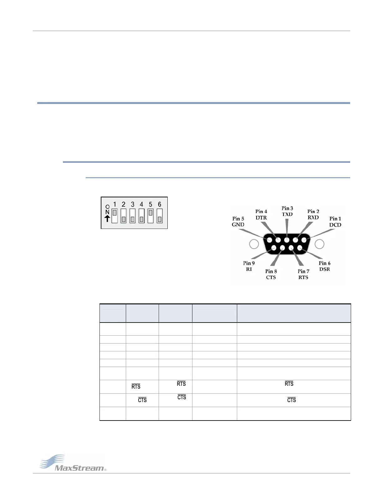
2.1.1. DIP Switch Settings & Pin Signals
Figure2‐01.Figure2‐02.
RS‐232DIPSwitchSettingsPinsusedonthefemaleRS‐232(DB‐9)
SerialConnector
DIPSwitchsettingsarereadandapplied
onlywhilepowering‐on.
Table2‐01. RS‐232SignalsandtheirimplementationsontheXTendRFModem
(Low‐assertedsignalsaredistinguishedbyhorizontallineoverpinname.)
DB-9 Pin
RS-232
Name
Pin
Reference
Name*
Description Implementation
1 DCD
GPO2 /
RX LED
Data-Carrier-Detect Connected to DSR (pin6)
2 RXD DO Received Data Serial data exiting the RF Modem (to host)
3 TXD DI Transmitted Data Serial data entering into the RF modem (from host)
4 DTR GPI2 / SLEEP Data-Terminal-Ready Can enable POWER-DOWN on the RF Modem
5 GND - Ground Signal Ground
6 DSR
GPO2 /
RX LED
Data-Set-Ready Connected to DCD (pin1)
7 / CMD
GPI1 /
/
CMD
Request-to-Send
Provides
flow control or
enables “Command Mode” on the RF Modem
8
GPO1 /
/
RS-485 TX EN
Clear-to-Send Provides
flow control
9 RI - Ring Indicator
Optional power input that is connected internally to the
positive lead of the front power connector
*ThePinReferenceNameprovidesanassociativetagthatreferencescommandsusedtodefinepinbehavior.
GPIstandsfor“GeneralPurposeInput”andGPOstandsfor“GeneralPurposeOutput”.Forexample,theCD
CommandisusedtodefinethebehaviorofGPIO2(pin1).