9XTend‐PKG‐R™RS‐232/485RFModem–ProductManualv1.2.4
©2005MaxStream,Inc.ConfidentialandProprietary 20
4. ModemConfiguration
4.1. Automatic DIP Switch Configurations
Each time an RF Modem is powered on, AT commands are sent to the on-board RF module as
dictated by the positions of the DIP switches. DIP switch configurations are sent automatically
during the power-on sequence and affect modem parameter values as shown in the table below.
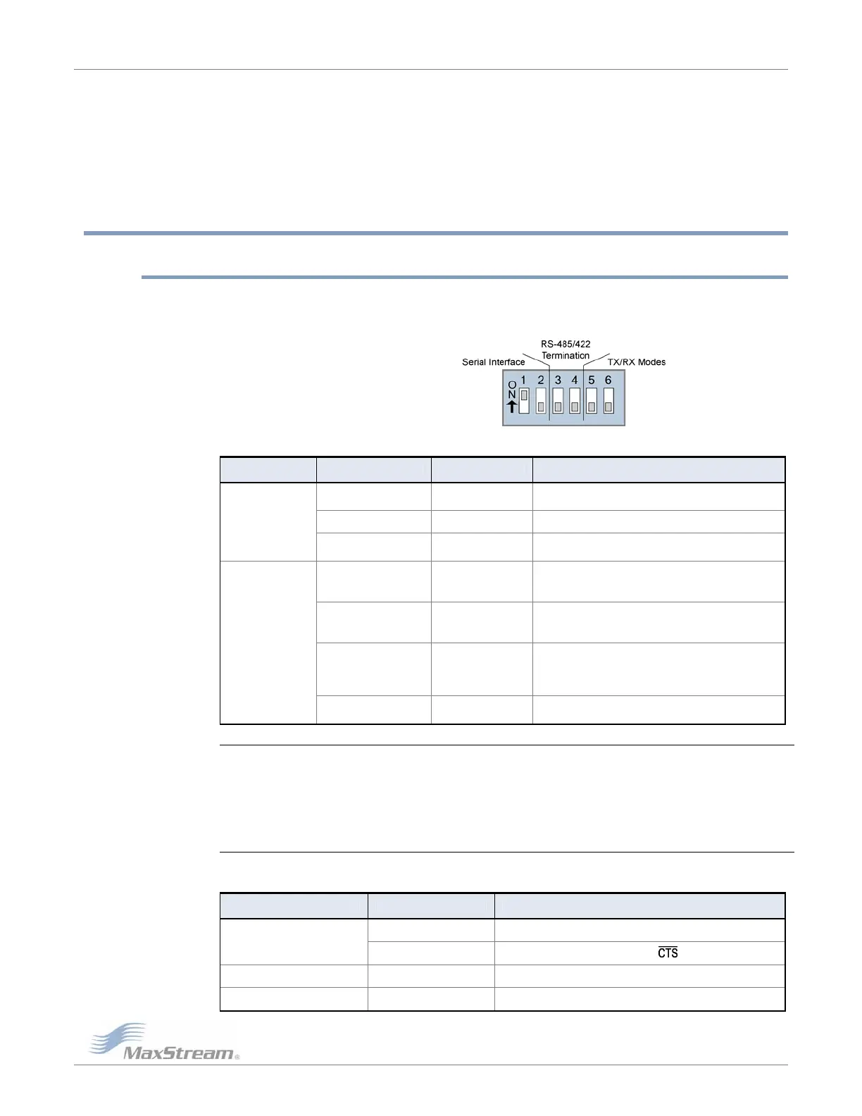
Figure4‐01. DIPSwitches
Table4‐01. Power‐upOptions‐CommandssentasresultofDIPSwitchSettings(SW=DIPSwitch)
Switches Condition Behavior Commands Sent During Power-up
If SW1 & SW2
are ON (up)
Restore Defaults
ATRE (Restore Defaults)
ATWR (Write defaults to non-volatile memory)
If SW1 is ON (up) RS-232 Operation ATCS 0 (RS-232, CTS flow control)
Switches 1 & 2
(Restore Defaults /
Serial Interfacing)
If SW1 is OFF (down)
RS-485/422
Operation
ATCS 3 (RS-485 or RS-422 Operation)
If SW5 is ON (up) &
SW6 is OFF (down)
Peer-to-Peer
ATAM (Auto-set MY, MY = unique)
ATDT FFFF (Destination Address)
ATMT 3 (Multi-Transmit option)
If SW5 & SW6 are
OFF (down)
Multipoint Base
ATMY 0 (Source Address)
ATDT FFFF (Destination Address)
ATMT 3 (Multi-Transmit option)
If SW5 is OFF (down) &
SW6 is ON (up)
Multipoint Remote
ATAM (Auto-set MY, MY = unique)
ATDT 0 (Destination Address)
ATMT 0 (Multi-Transmit option)
ATRR A (Retries)
Switches 5 & 6
(TX/RX Modes)
If SW5 is ON (up) &
SW6 is ON (up)
User Defined
Processor is disabled and AT Commands are not sent to
the modem (except for CS command as shown below.)
IMPORTANT: To avoid overwriting previously stored custom configurations (due to the automatic
configurations that take place each time the RF modem is powered-on), it is necessary to disable a
processor located inside the RF modem.
To disable the processor, turn switches 5 and 6 ON (up). When switches 5 and 6 are ON, only the CS
command is sent [refer to table below].
Table4‐02. UserDefinedMode(Switches5and6areON(up))
DIP Switches ON (up) Condition Command Sent During Power-up
If CS = 0, 1, 2 or 4 CS parameter remains the same
SW1, SW5 and SW6
If CS = 3 ATCS 0 (RS-232 operation,
flow control)
SW2, SW5 and SW6 If CS = 2 ATCS 2 (GPO1 high)
SW5 and SW6 only If CS = 0, 1, 2, 3 or 4 ATCS 3 (RS-485/422 Operation)