Make sure that you have a good chassis ground. Good ground connections will eliminate
most electrical noise problems. A good chassis ground requires a tight connection to the
vehicle's metal chassis. The area around the ground connection should be clean, bare
metal without rust, paint, plastic, dust, or dirt for a good electrical connection.
Speaker Wiring Notes
Follow the above wiring diagram to
install the head unit with new or existing
speakers.
This unit is designed for use with four (4)
speakers with an impedance between 4
Ohms to 8 Ohms.
An impedance load of less than 4 Ohms
could damage the unit.
Never bridge or combine the speaker
wire outputs. When not using four
speakers, use electrical tape to tape
the ends of the un-used speaker outputs to
prevent a short circuit.
Never ground the negative speaker
terminals to chassis ground.
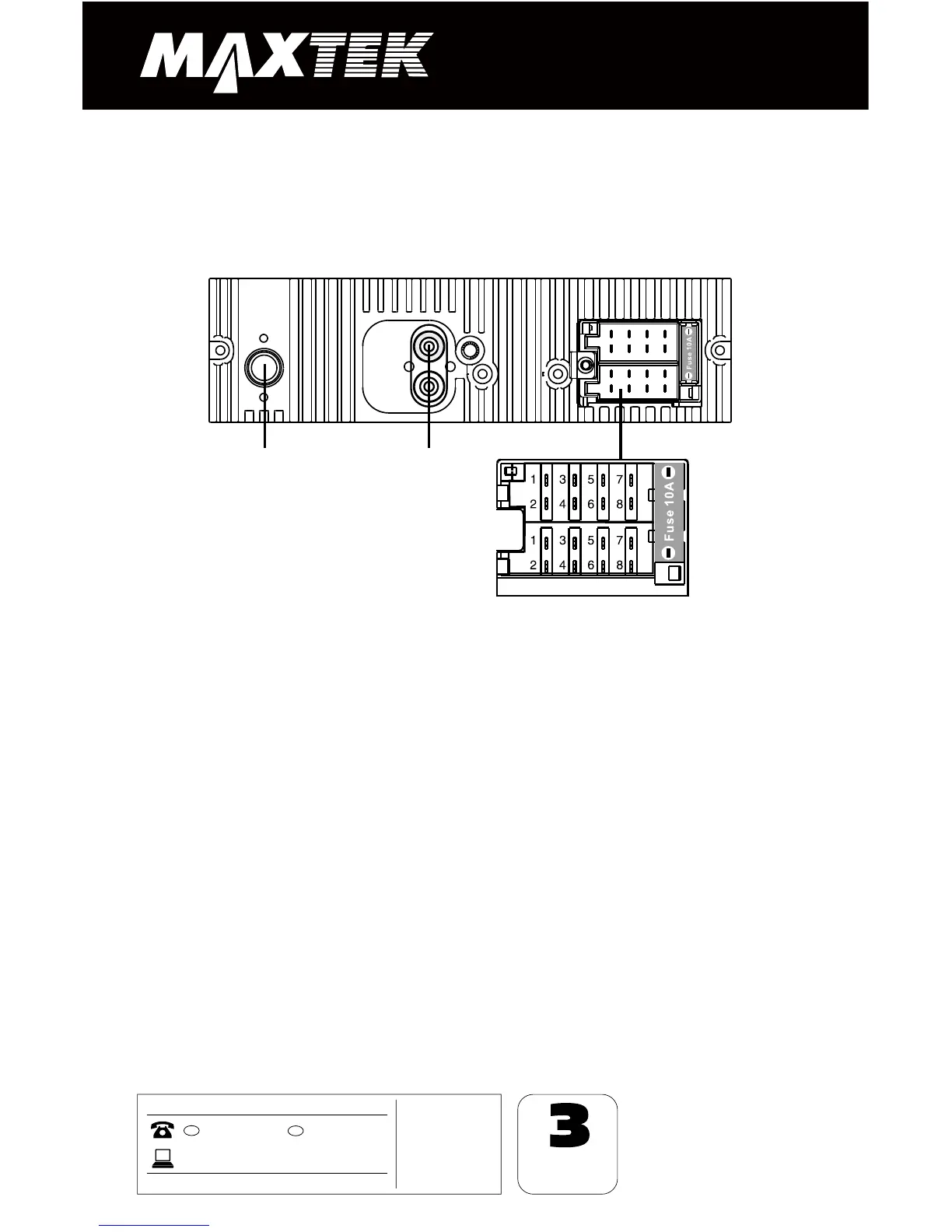
Wiring Connection
Connector A
1. Rear right speaker(+)/Blue
3. Front right speaker(+)/Grey
5. Front left speaker(+)/Green
2. Rear right speaker(-)/Blue-White
4. Front right speaker(-)/Grey-White
6. Front left speaker(-)/Green-White
7. Rear left speaker(+)/Brown
8. Rear left speaker(-)/Brown-White
Connector B
1. -
2. -
3. -
4. Battery 12V (+)/Yellow
5. Antenna power/Orange
6. Panel light/White
7. ACC+/Red
8. Ground/Black
ISO-connector
A
B
RCA OUT
left=white
right=red
Antenna
socket