15
Publication: ZTS-080812
M-B Companies, Inc. 11/15/12
INTRODUCTIONADJUSTMENT AND SERVICE
6. Route the belt from the lower center pulley under the tension
pulley.
7. Position the belt under the two front pulleys and up to the broom
drive pulley.
Figure 17
8. When the belt is in position, pull out on the lever to engage the
tensioner.
9. To install the rear V-belt to the engine pulley refer to the
Attachment Mount Installation manual.
SHEAR PIN REPLACEMENT
DANGER! Do not go near the broom when the
engine is running. Do not run the engine
with any cover or guard removed.
Under most circumstances, if the broom strikes an object which could
cause damage to the unit, the shear pin(s) will break. This protects the
gear box and other parts from damage. The shear pins are located on
the broom shaft.
See Figure 18 Shear Pin Replacement.
To replace the shear pins:
1. Tap out the broken pin(s) with a pin punch.
IMPORTANT! Do NOT replace shear pins with anything other
than the correct grade replacement shear pin.
Use of bolts, screws or a harder shear pin will
lead to damaged equipment.
2. Install new shear pin(s) and secure with nut.
Figure 18 Shear Pin Replacement
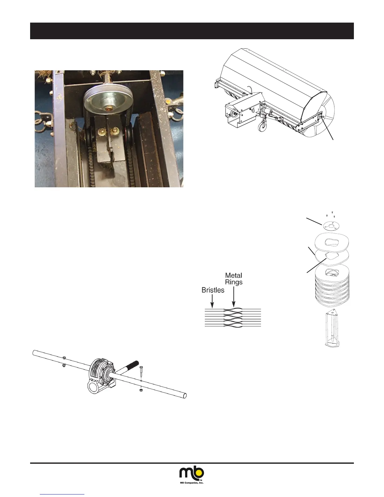
BRUSH SEGMENT REPLACEMENT
1. Remove bolts from broom bearings at both ends of the support
shaft (Figure 19 Brush Removal).
Attachment Bolts
Figure 19 Brush Removal
2. Loosen bearing setscrews and slide bearings inwards toward
the center of broom.
3. Move power unit backwards away from the brush assembly. The
brush and gearbox will pull free from the drive pulley shaft.
IMPORTANT! Support splined drive shaft to prevent damage.
4. Stand broom assembly on one end. (See Figure 20 Brush
Assembly)
A. End Plate C. Engagement Fingers
B. Brush Segment
Positioned Hill to Hill
Valley to Valley
A
B
C
Figure 20 Brush Assembly
5. Remove the three bolts from the end plate (See A, Figure 20
Brush Assembly).
6. Remove used broom segments.
7. Install new broom segments. Position the segment cores to
provide hill to hill valley to valley contact.
NOTE: Align segment engagement ngers (C, Figure 20 Brush
Assembly) on alternating support shafts. This will evenly
spread rotating force through the drive system.
8. Reinstall broom assembly.
IMPORTANT! Fully tighten the bearing setscrews before
operating the power broom.