Adjustment
15
Adjustment
This section describes:
• Checking motor rotation
• SmarTraq Programmer Controls
• Learning Full Open and Full Close positions
• Verifying Operation
• Adjusting parameters
Checking Motor Rotation
Motor control connections from inverter drive terminals TB2 and TB3 to the motor assume
clockwise motor rotation when the elevator doors are closing. It is important to verify that this
is the case:
1. Manually open and close elevator doors while watching motor rotation.
2. Viewed from the motor shaft end, motor must rotate clockwise when doors are closing.
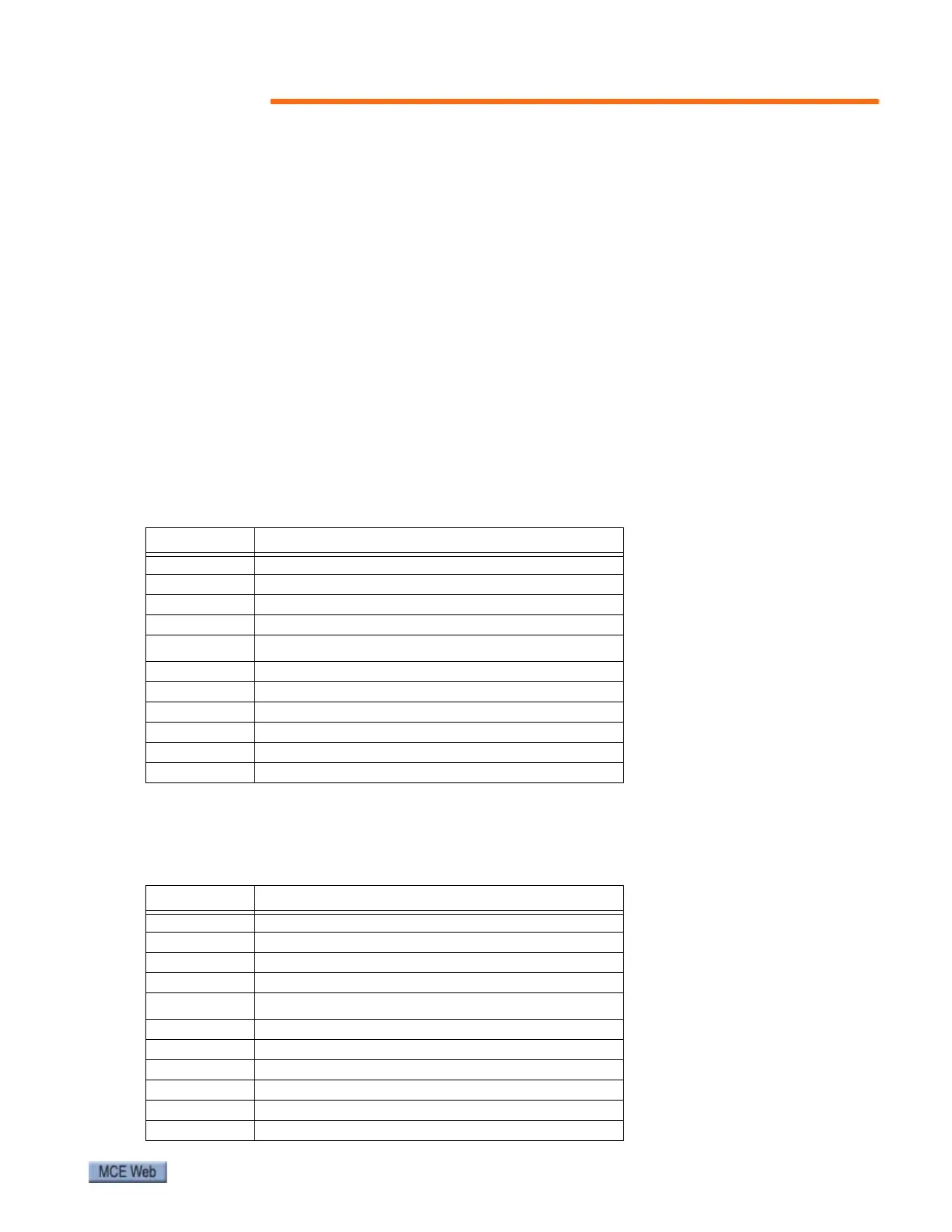
If so, connections shown in the wiring diagram and in the table below are correct:
3. If, as viewed from the shaft end, motor rotates counter-clockwise when doors are clos-
ing, connections must be changed as shown in the following table:
Table 2. Motor Connections from Wiring Diagram
Motor TB2 Connector
U1 Terminal 1
V1 Terminal 2
W1 Terminal 3
NTerminal 4
TB3 Connector
SOUT Terminal 9
ENC0 (white) Terminal 8
ENC1 (blue) Terminal 7
-E Terminal 6
-S Terminal 5
+S Terminal 1
Table 3. Motor Connections if Rotation is Counter-Clockwise as Doors Close
Motor TB2 Connector
U1 Terminal 1
V1 Terminal 3 (changed)
W1 Terminal 2 (changed)
NTerminal 4
TB3 Connector
SOUT Terminal 9
ENC0 (white) Terminal 7 (changed)
ENC1 (blue) Terminal 8 (changed)
-E Terminal 6
-S Terminal 5
+S Terminal 1