SmarTraq
40 Manual # 42-02-D008 Rev. A2
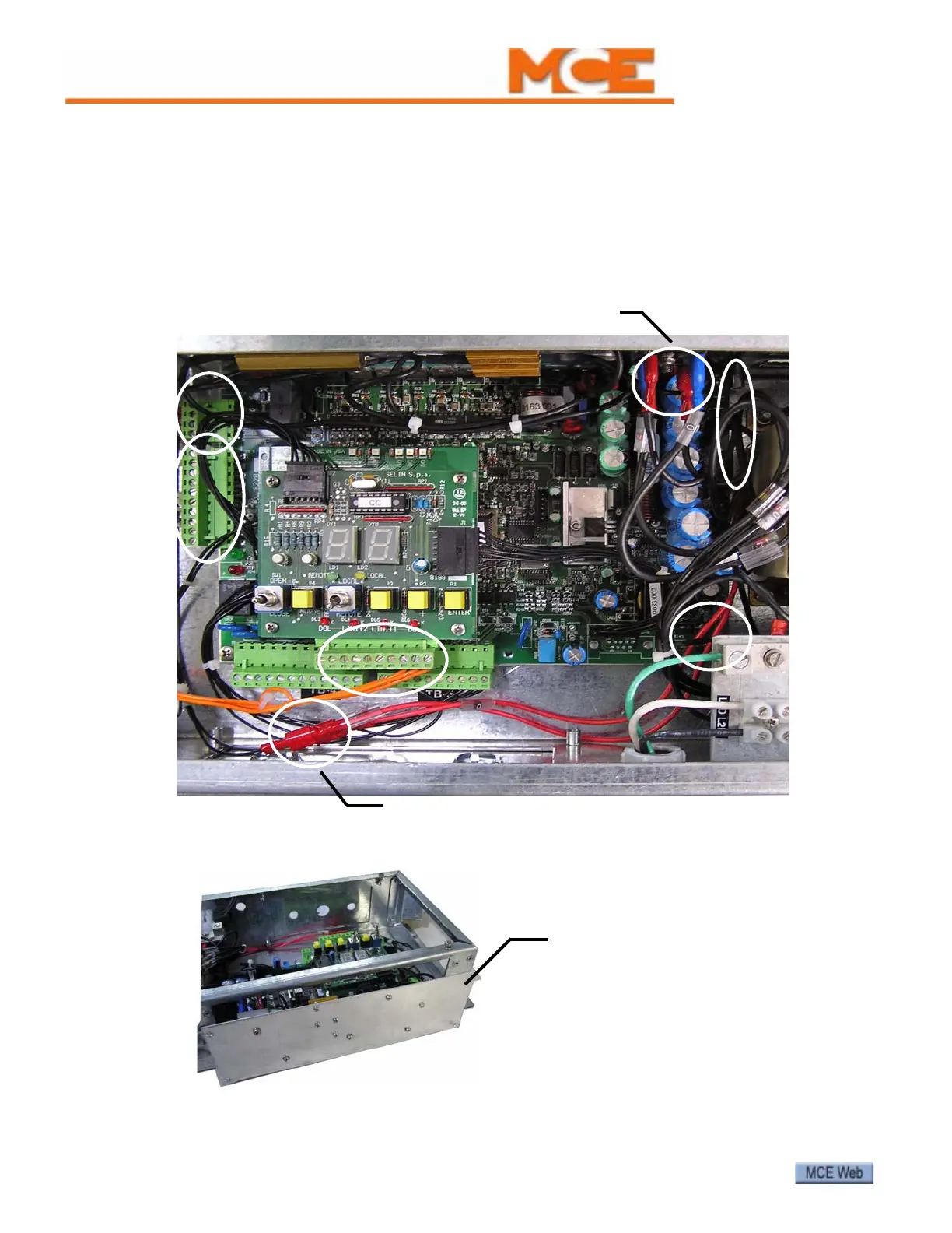
Board Set Replacement
DO NOT remove or attempt to repair individual boards! If necessary, the entire board set is
replaced as a single unit. The circuit board set is designed for easy field replacement:
1. Remove the cover from the drive enclosure. Power down the unit.
2. Unplug signal wire connections to board set. Locations A, B, and C.
3. Disconnect power and ground connections to board set and connections to over voltage
protection unit. Locations D, E, F, and G.
4. Remove the four screws securing the board set cover plate in place. (The screws have a
yellow dot adjacent to them.) Slide the board set out.
5. Install the new board set. Reconnect wiring.
6. Power up. Perform door learn process and adjust parameters as needed.
A
B
C
D
E
F
M/F pigtail leads. Red wires.
0V and 28V pigtails
(blue)
G
Remove four retaining screws.
Slide board set out.
Replacement board set:
HC-DO-DRIVE-MODULE