25
Figure 16
The Rear Panel Trigger B Jack can provide either a 5 or 12
Volt Output when activated, with 5 Volts as the default.
McIntosh Components with Power Control utilize 5 Volts;
non-McIntosh components when connected to the C1000C
might required a higher voltage to switch them On or Off.
To change the output voltage to 12 volts follow the steps
below:
1. Press the SETUP Push-button once to access the Setup
Controller Mode unless the C1000C is already in the
Setup Controller Mode.
2. Rotate the BALANCE (Menu) Control until the words
“TRIGB LVL 5V” appears. Refer to figure 16.
3. Rotate the LISTEN (Select) Control until the Front
Panel Alphanumeric Display indicates “TRIGB LVL
12V”. Refer to figure 17.
4. If no other adjustments are to be made at this time,
press the SETUP Push-button to exit the Setup Control-
ler Mode or proceed to the next desired Setup Control-
ler Mode for adjustment.
Trigger B Voltage (Power Control)
Setup, con’t
4. If no other adjustments are to be made at this time,
press the SETUP Push-button to exit the Setup Control-
ler Mode or proceed to the next desired Setup Control-
ler Mode for adjustment.
Figure 17
Triamp (Balanced Outputs)
The C1000P and/or C1000T Preamplifiers provides three
Balanced XLR Output Connectors for each channel. One
Output is labeled MAIN (non-switched) and two additional
Outputs MAIN/SPKR1 and MAIN/SPKR2 (switched On
or Off by using the HR54 Remote Control ). Outputs
MAIN/SPKR1 and MAIN/SPKR2 may be configured to
remain On along with the MAIN Output for use in systems
with three Power Amplifiers per channel. To change the
MAIN/SPKR1 and MAIN/SPKR2 Outputs perform the fol-
lowing steps:
1. Press the SETUP Push-button once to access the Setup
Controller Mode unless the C1000C is already in the
Setup Controller Mode.
Figure 18
Figure 19
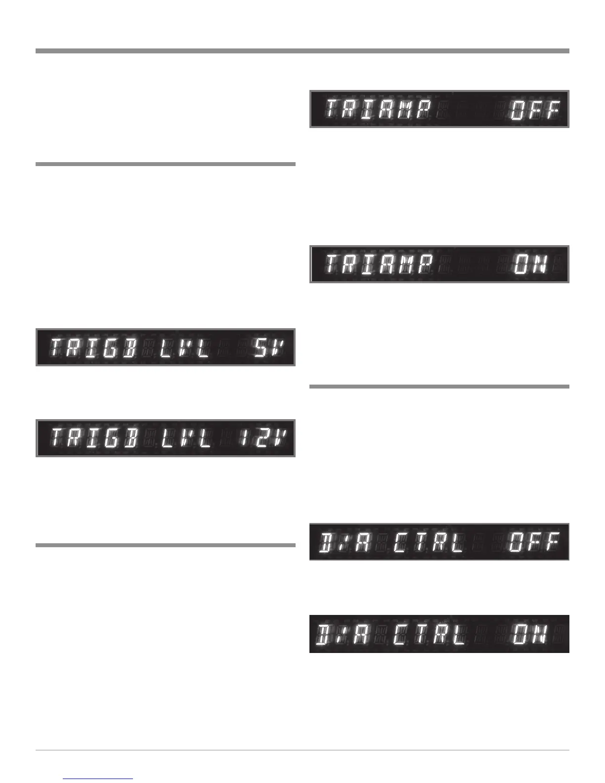
2. Rotate the BALANCE (Menu) Control until the words
“TRIAMP OFF” appears. Refer to figure 18.
3. Rotate the LISTEN (Select) Control until the Front
Panel Alphanumeric Display indicates “TRIAMP ON”.
Refer to figure 19.
Note: The Unbalanced SPKR1 and SPKR2 Main Outputs
are still controllable (On or Off) with the HR54
Remote Control.
4. If no other adjustments are to be made at this time,
press the SETUP Push-button to exit the Setup Control-
ler Mode or proceed to the next desired Setup Control-
ler Mode for adjustment.
D/A Control (McIntosh MDA1000)
When the McIntosh MDA1000 D/A Converter and
MCD1000 CD Player are connected to the C1000 Control-
ler there are special functions to enhanced operation of the
D/A Converter with the C1000. The following steps activate
these functions:
1. Press the SETUP Push-button once to access the Setup
Controller Mode unless the C1000C is already in the
Setup Controller Mode.
2. Rotate the BALANCE (Menu) Control until the words
“D/A CTRL OFF” appears. Refer to figure 20.
3. Rotate the LISTEN (Select) Control until the Front
Panel Alphanumeric Display indicates “D/A CTRL
ON”. Refer to figure 21.
Figure 20
Figure 21
 Loading...