21
Control Circuit is unacceptable for use in the C2300, as
it does not match the classic McIntosh Volume Control
Audio Taper. The C2300 incorporates electronic circuitry
together with sophisticated firmware to produce electroni-
cally the classic McIntosh Volume Control Audio Taper,
while maintaining the channel balance and freedom from
control noise.
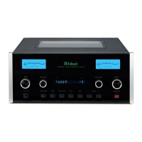
The Volume Control on the Front Panel of the C2300 is
actually a special digital optical encoder. As the Volume
Control is rotated, a beam of Infra Red Light is picked up
by two internal sensors as a series of digital pulses. Refer
to the exploded view in figure
29. The number of and time
between pulses are counted by
a Microprocessor which in turn
controls the McIntosh designed
Precision Electronic Attenua-
tor that provides 213 steps in
0.5dB increments and maintains
the channel balance to within +
0.1dB.
With most Preamplifiers the Volume Control is placed
ahead of the Amplifying Circuitry providing large dynam-
ic range and freedom from input overload however, back-
ground noise level is higher at lower settings of the volume
control. By placing the Volume Control after the Amplify-
Technical Description
ing Circuitry there is lower background noise however,
a reduction in dynamic range and input overload is the
result. The only correct way to design a high performance
Preamplifier is with two volume controls. This provides
the benefits of wide dynamic range, freedom from Input
overload and a background noise level that actually goes
down as the volume control setting is reduced. The special
controlling circuitry for this dual volume control design is
known as the McIntosh “Dynamic Control Multiplexer”.
Meter and Circuitry
McIntosh solved the problems with ordinary meters in
the C2300. By developing electronic circuits the meters
are made to respond to short intervals with an accuracy
of 95%! To permit the eye to see such high speed motion,
the electronic circuits that drive the meter pointer are time
stretched. Special logarithmic circuitry allows the meter
to indicate a 60dB plus range, without resorting to a Meter
Range Switch.
Power Supply Circuits
To compliment the design of the C2300 there are fully
regulated power supplies. The special “R” core transform
-
ers supplies the necessary voltage/current for the low and
high voltage regulated circuitry.
Figure 29
Infrared
LED
Optical Disc
Sensors
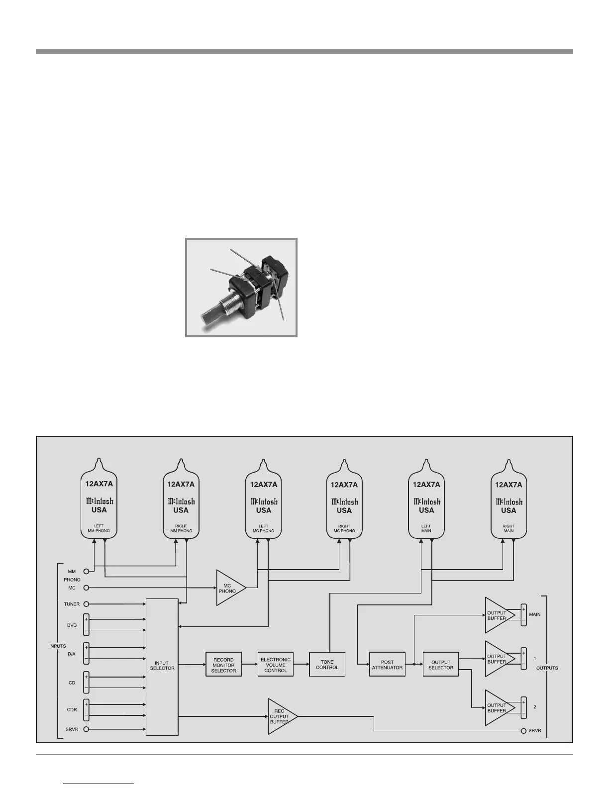
C2300 Block Diagram
 Loading...