5. Install the Mounting Strips
In the hardware package you will find two mounting
strips, and two sets of machine screws. For panels
that are less than 1/2 inch (12.7 mm) thick, use the
3/4 inch (19.1 mm) screws; for panels that are more
than 1/2 inch (12.7 rnrn) thick, use the 1-1/4 inch (31.8
mm) screws.
Starting at the right-hand side of the panel, insert a
screw of the proper length into the center hole in
the panel, marked B on the template. On the back of
the panel, align a mounting strip with the holes in
the panel and tighten the screw until the screwhead
is pulled into the wood.
Repeat this procedure to attach the mounting strip
to the left side of the panel.
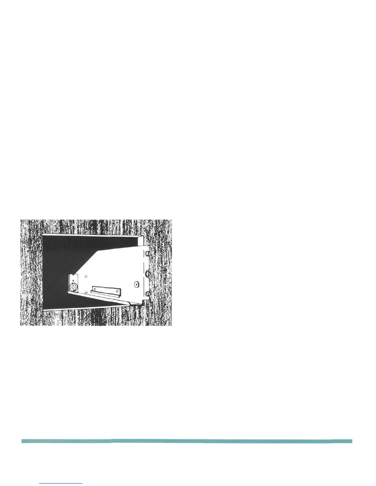
6. Attach the PANLOC Brackets
Using two screws of the proper length in the A holes
on each side, attach the PANLOC brackets to the
cabinet panel; the short flange is mounted against
the front (face) of the cabinet panel. The screws pass
through the PANLOC bracket flange, the cabinet
panel, and then through the mounting strips
previously mounted.
the cabinet. Turn the PANLOC buttons
counterclockwise to unlock the instrument. It can
then slide outward to permit the removal of the
instrument from the cabinet.
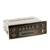
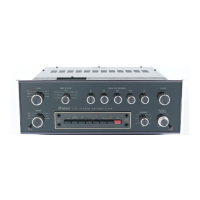
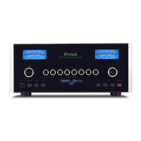
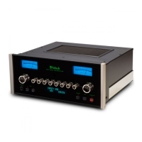
7. Install the Instrument
Guide the AC power cord through the panel opening
to the back of the cabinet; then, slide the instrument
into the opening carefully so that the rails on the bot-
tom of each side of the chassis engage the tracks on
the mounting brackets. Continue to slide the
instrument into the cabinet until the front panel is
flush with the cabinet panel. Turn the PANLOC
buttons at the lower left and right corners of the
instrument panel clockwise to lock the unit firmly in
INSTALLATION 7
 Loading...