7
Connecting Components
The identification of Rear Panel Connections for the
C49 Audio Preamplifier is located on a separate folded
sheet contained in the Owner’s Manual Packet.
Refer to separate sheet “Mc2B” for the Rear Panel
Connections.
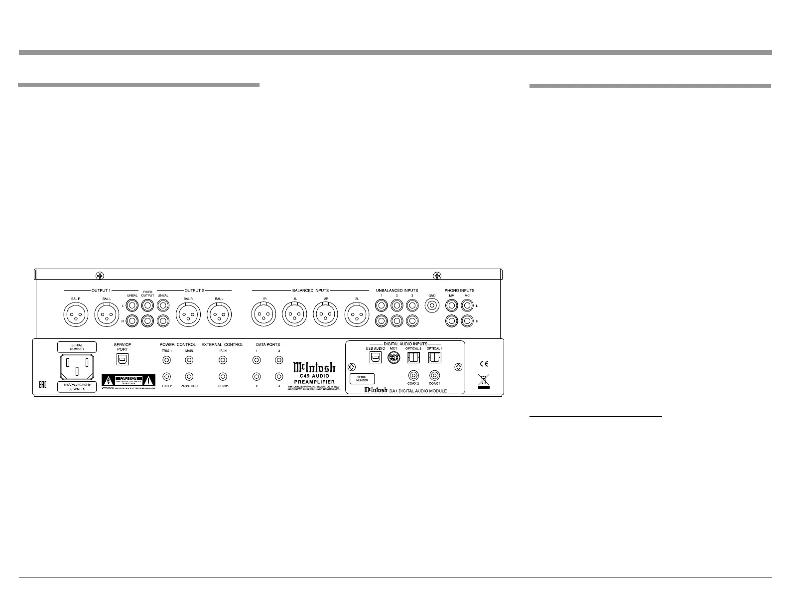
Rear Panel Connections
C49 Audio Preamplifer Rear Panel
The C49 has the ability to automatically switch power
On/Off to Source Components via the Power Con-
trol connections. The Data Port Connections allow
for the remote operation of basic functions using the
C49 Remote Control HR085. With an external sensor
connected to the C49, remote control operation of the
system is possible from another room and/or when the
C49 is located in a cabinet with the doors closed.
The connection instructions below, together with
the C49 Input/Output/Control Connection Diagrams
located on the separate folded sheets “Mc1A/1B and
Mc2A”, are an example of a typical audio system.
Your system may vary from this, however the actual
components would be connected in a similar manner.
For additional information refer to “Connector and
Cable Information” on page 3.
Notes: 1. The C49 allows renaming of the Audio Inputs
Names as indicated on the Front Panel Infor-
mation Display. Example, “UNBAL 1” may be
changed to “TUNER” or your own personal
preference. Refer to Setup “Renaming Input” on
page 14.
2. For convenience, an “Input Assignment Chart”
on a separate sheet “Mc5A/5B” has been pro-
vided to keep track of changes.
Power Control Connections:
1. Connect a Control Cable from the C49 POWER
CONTROL MAIN Jack to the Power Control In
on the Turntable.
2. Connect a Control Cable from the Turntable Pow-
er Control Out Jack to the Digital Audio Player
Trigger In Jack.
3. Connect a Control Cable from the Digital Audio
Player Trigger Out Jack to the SACD Transport
Power Control In Jack.
4. Connect a Control Cable from the SACD Trans-
port Power Control Out Jack to the Tuner Power
@
(.ji:\
---OUTPUT1---
A><ED
---OUTPUT2---
BALANCED
INPUT
S UNBALANCED
IN
PUTS
P
HONO
INPUT
S
UNBAI.
OUTPUT
U
NBAI.
1
23
GNDMMMC
lR
1L
~
"
''" ''"
@@
@
'""
''"
~~~
~
@@@@@@
,
~~::::~~
@@@
@@
A
I
SERIAL
I
SERVICE
POWER CONTROL
EXTERNA
L CONTROL
DATAPOATS
-
DIGITAL
AUDIO
INPUT
S-
NUMBER
POAT
mo,
"'"
IA
IN
'
3
U
SB
A
UDIO
MCT
O""""-'
OPTICAL1
w
~
@ @ @ @ @
ffit(nfosh
@
~@
l!I!I
l!I!I
(€
@
I
ffl'!!
t:::::..m
r,1
@ @ @ @ @
C49
AUDIO
~
(®)
(®)
~
ERC
I
PREAMPLIFIER
'
co.ax, oo,x,
120Vl'\,,50/60Hz
TAIG2 PASSTHRU
"""
'
.
~I.MIOAATCl!T
.NC.liMlHMmlN,N'f l!lllll
30WA
TT
S
ATTElfOON:
MO.E
Of:C>O:~
...
-
IWll(1W'TB)fl~WITHlOSN<CIIFUUHIPMTll
ffltlnlosh
DA1 0IGITAL
Au
o,0
Mo
ouLE