10
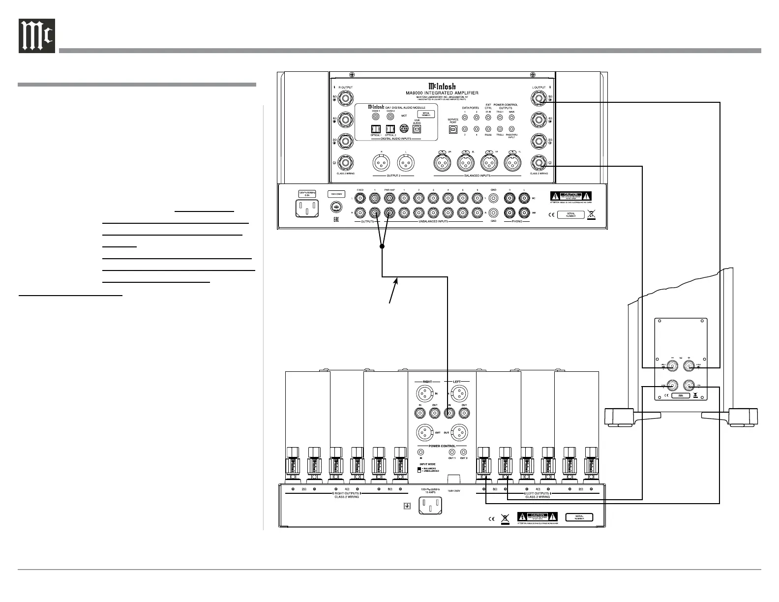
The MA9000 Power Amplifier Circuitry, together
with an additional separate Power Amplifier, may
be used to Bi-Amplify a Loudspeaker System. In the
illustration on this page, the Power Amplifier of the
MA9000 is connected to the Midrange/High Fre-
quency Section of the Loudspeaker. The additional
separate Power Amplifier is connected to the Low
Frequency Section of the Loudspeaker System.
Warning: The Loudspeaker System used for
Bi-Amplification must have the
jumpers removed from between the
MID/HIGH and LOW Frequency
Sections of the Loudspeaker System.
Failure to remove them could result
in damage to the MA9000 and/or the
separate Power Amplifier.
MA9000 Connections:
1. Remove the “McIntosh Jumpers” from between
the OUTPUT 1 Jacks and the PWR AMP In Jacks
located on the Rear Panel of the MA9000.
Note: Place the “McIntosh Jumper” in a safe place
for possible future use.
2. Using a pair of shielded RCA Type Audio “Y”
Adapters connect the OUTPUT 1 Jacks to the
PWR AMP In Jacks, for both Left and Right
Channels.
3. Connect the remaining unconnected part of the
“Y” Adapters to the separate Power Amplifier.
4. Referring to the Loudspeaker Connection Instruc-
tions on page 11, and in the Owner’s Manual sup-
plied with the Power Amplifier and Loudspeaker,
connect the MA9000 Output Terminals to the
Loudspeaker MID/HIGH Input Terminals.
Note: The Loudspeaker Connection illustrations
on this page are for the Left Channel. Con-
nect the Right Channel Loudspeaker in the
same manner.
Connecting for Bi-Amplification
Connecting for Bi-Amplification
+
-
Left Channel
Loudspeaker
“Y” adapter Cable
Power Amplier
 Loading...