EasyManuals Logo

McIntosh MC 7300 User Manual

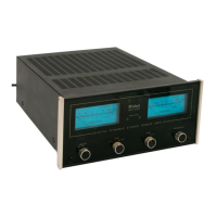
McIntosh MC 7300
20 pages
To Next Page IconTo Next Page
To Previous Page IconTo Previous Page
Page #17 background imageLoading...
Page #17 background image
ОМЕЕ
GUARD
Power
Guard,
a
unique
feature
of
McIntosh
amplifiers,
assures
that
each
channel
of
the
MC
7300
will
deliver
full
power
free
of
clipping
distortion.
Clipping
is
caused
when
an
amplifier
is
asked
to
pro-
duce
more
power
output
than
its
design
is
capable
of
delivering
with
low
distortion.
Amplifiers
that
are
overdriven
may
deliver
large
quantities
of
power
when
they
are
clipping,
but
they
may
have
more
than
4096
harmonic
distortion.
In
this
mode,
the
sound
is
grossly
distorted
and
the
extra
energy
con-
~
tent
of
the
clipped
signal
will
damage
most
loud-
speakers.
The
McIntosh
Power
Guard
circuit
protects
your
ears
and
your
speakers
from
this
kind
of
damage.
The
Power
Guard
circuit
consists
of
a
waveform
comparator
which
monitors
the
wave
shape
of
the
amplifier
input
and
output
signals.
Normally,
there
is
no
disparity
between
these
signals
and
the
com-
parator
produces
no
output.
When
the
amplifier
is
driven
beyond
its
maximum
power
capacity,
a
dif-
ference
will
develop.
If
the
disparity
exceeds
0.3%
(equivalent
to
0.39
total
harmonic
distortion),
the
comparator
output
causes
the
amber
Power
Guard
indicator
to
light.
If
there
is
a
further
increase
in
the
~
врату,
the
comparator
output
controls
an
elec-
г
onic
attenuator
at
the
amplifier
input
to
reduce
the
amplifier
gain,
thus
holding
the
amplifier
output
to
a
low
distortion
value.
Overdrive
by
14dB
is
possible
before
the
output
distortion
exceeds
296.
SENTRY
MONITOR
All
power
transistors
have
limits
for
the
maximum
amount
of
power
they
can
handle.
The
MC
7300
out-
put
transistors
and
power
supply
have
been
design-
ed
to
allow
very
high
current
flow
into
properly
matched
load
impedances.
If,
however,
a
short
cir-
cuit
or
very
low
value
of
load
impedance
is
applied
to
the
output
of
the
MC
7300,
destructive
current
levels
could
be
reached
if
it
was
not
controlled
by
the
Sentry
Monitor
circuit.
This
circuit
senses
the
“dynamic
operating
time,
voltage,
and
current
of
the
amplifier
output
stage
and
controls
the
current
flow
confining
it
to
nondestructive
limits.
Sentry
Monitor
does
not
limit
the
power
output
available
from
the
amplifier.
THERMAL
CONTROL
АП
power
transistors
have
limits
for
the
maximum
amount
of
heat
they
can
tolerate.
The
MC
7300
uses
a
highly
efficient
amplifying
circuit
which
produces
relatively
little
heat
for
the
output
power
produced.
The
amplifier
has
4
oversized
heatsinks
to
dissipate
tran-
sistor
generated
heat.
Natural
convection
air
flow
is
suf-
ficient
for
cool
operation.
Should
the
cooling
air
be
blocked
or
should
the
amplifier
operating
temperature
become
too
high,
thermal
cutouts
within
the
amplifier
will
turn
off
the
power
to
the
amplifier.
When
the
amplifier
has
cooled,
it
will
automatically
turn
on
again.
TURN-ON
DELAY
The
MC
7300
has
a
turn-on
delay
circuit
that
delays
amplifier
operation
for
about
2
seconds
after
power
turn-on.
This
prevents
pops
or
thumps
generated
in
other
equipment
from
causing
annoying
noises
or
damaging
your
loudspeakers.
DIRECT
CURRENT
FAILURE
PROTECTION
The
autotransformer
protects
speakers
from
damage
in
the
event
of
amplifier
failure.
Should
a
direct
current
component
appear
in
the
output,
it
is
shunted
by
the
autotransformer
and
DC
cannot
reach
the
speaker.
POWER
LINE
INRUSH
PROTECTION
Turn-on
inrush
current
is
cushioned
by
thermistors
in
the
power
transformer
primary
circuit.
A
soft
start
is
achieved
that
eliminates
component
stress
during
turn-on.
CIRCUIT
OPERATION
The
audio
input
passes
through
the
gain
control
to
a
preamplifier.
The
output
amplifier
is
driven
by
the
preamplifier.
The
power
output
amplifier
uses
two
stages
of
voltage
amplification
followed
by
three
stages
of
cur-
rent
amplification.
All
stages
are
complementary
balanced.
Even
number
harmonics
are
cancelled
by
the
balanced
circuits.
This
means
that
the
amplifying
stages
have
less
total
harmonic
distortion
and
less
negative
feedback
is
required
to
achieve
ultra
low
distortion.
The
signal
is
fed
to
one
input
of
the
balanced
dif-
ferential
stage.
Feedback
from
the
amplifier
output
is
applied
to
the
other
input.
The
differential
amplifiers
drive
a
balanced
cascode
connected
voltage
amplifier
stage.
Current
mirrors
are
also
used
to
improve
bandwidth
and
linearity.
The
cascode
voltage
amplifier
output
feeds
com-
plementary
Darlington
connected
driver
transistors.
These
supply
the
signal
to
10
complementary
con-
nected
output
transistors
per
channel.
Ancillary
com-
ponents
for
Power
Guard,
Sentry
Monitor,
Power
Output
Meters
and
other
protection
circuits
inter-
TECHNICAL
DESCRIPTION
15

Other manuals for McIntosh MC 7300

Questions and Answers:

Question and Answer IconNeed help?

Do you have a question about the McIntosh MC 7300 and is the answer not in the manual?

McIntosh MC 7300 Specifications

General IconGeneral
BrandMcIntosh
ModelMC 7300
CategoryAmplifier
LanguageEnglish

Related product manuals