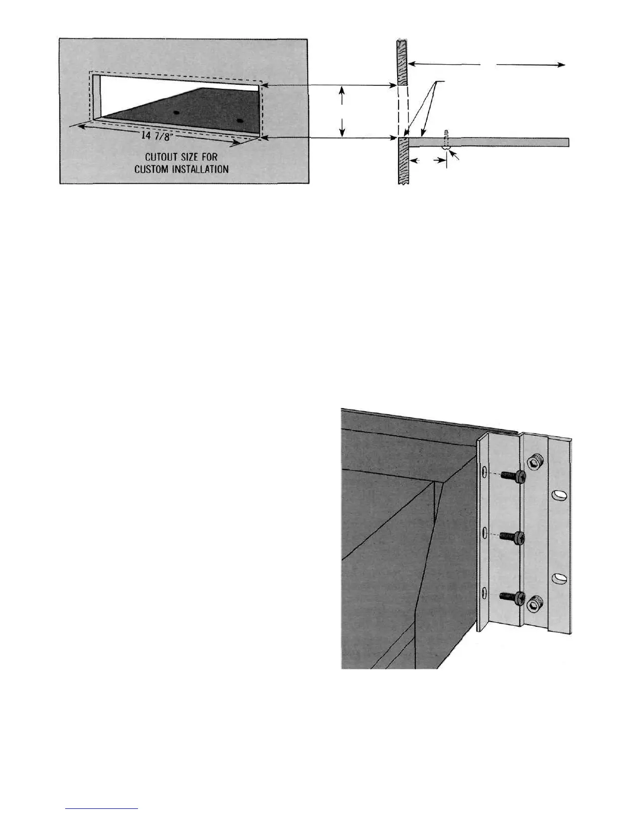
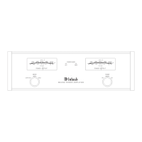
Fig. 2. Views showing mounting shelf in position.
INSTALLATION PROCEDURE
1. Mark for Position
Mark cabinet panel where the instrument is to be
installed. The solid lines in Fig. 2 represent the outline of
the rectangular cutout and also represent the outside
dimensions of the chassis. Make sure these lines clear
shelves, partitions, or any equipment. The broken line
represents the outside dimension of the panel.
2. Drill Holes
Using a drill bit slightly wider than the tip of your saw
blade, drill one hole at each of two diagonally opposite
corners. The holes should barely touch the inside edge of
the outline.
3. Saw Panel Cutout
Sawing carefully on the inside of the lines, first make
the two long cuts and then the two short. After the
rectangular opening has been cut out, use a file to
square the corners and smooth any irregularities in the
cut edges.
4. Shelf Installation
Install the shelf on which the MC 2200 will sit. It
must be capable of supporting the total weight of the
instrument. Drill the two ¼" holes shown in Fig. 1.
5. Install Instrument
Guide the AC power cord through the panel opening
to the back of the cabinet; then, slide the instrument into
the opening until its front panel is flush with the cabinet
panel. Secure the MC 2200 to the shelf with #10 wood
screws of the proper length.
½" thick shelf—use 1" screws
5
/
8
"
thick shelf—use 1
1
/
8
"
screws
¾" thick shelf—use 1¼" screws
Do not use screws longer than this recommended
length. They may penetrate electronic components
inside the chassis and cause severe damage. In any
event, the screw length must not exceed the shelf
thickness by more than ½".
Insert two proper length screws through the mount-
ing shelf and into the holes in the bottom of the ampli-
fier. Do not overtighten the screws.
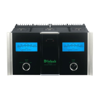
INSTALLATION IN A 19 INCH RACK
• The RACK MOUNTING ADAPTERS install on each end of
the front panel. On each side of the amplifier, three screws
secure the front panel bracket to the chassis. These three
screws are removed, the RACK MOUNTING ADAPTER
placed over the screw holes and the screws replaced. The
entire weight is transmitted through the RACK MOUNTING
ADAPTERS to the rack. No weight is carried by the front
panel. Additional support for the weight can be provided
at the rear of the chassis as desired.
Fig. 3. Rack Mounting Adapters installed.
3
6 9/16"
DEPTH REQUIRED
15".
TOP OF SHELF & BOTTOM
OF CUTOUT SHOULD COINCIDE.
SHELF
MOUNTING SCREWS
DIFFERENCE BETWEEN SCREW
LENGTH & TOTAL SHELF THICKNESS
MUST NOT EXCEED 1/2"
3"