INSTALLATION
Adequate ventilation should always be
provided in the installation of electronic
instruments. The trouble free life of these
instruments can be extended by adequate
ventilation. It is generally found that each 10°
centigrade (18°F) rise in temperature re-
duces the life of electrical insulation by one
half. Adequate ventilation is an inexpensive
and effective means of preventing insula-
tion breakdown because of unnecessarily
high operating temperatures. The direct
benefit of adequate ventilation is longer,
trouble free life.
The suggested minimum space for mount-
ing the MC225 is 16" long x 10" wide x 10"
high. Always supply ventilation holes in the
bottom of the amplifier mounting space and
a means for the warm air to escape at the top.
The MC225 can be mounted in any posi-
tion except upside down. If the amplifier is
to be installed on a vertical surface it is
recommended that the transformers be on
the down side. The advantage of this posi-
tion is that the flow of heat from the tubes
rises vertically and does not tend to heat
the transformers.
if the MC225 is to be permanently mounted
use the two mounting flanges supplied with
the amplifier. The flanges are shipped
separately and must be attached to the
amplifier bottom at each end.
Turn the MC225 over with the trans-
formers down and place it on a piece of cloth
or cardboard to prevent scratches. The
amplifier is shipped with 4 plastic feet on the
bottom cover. Remove the 4 plastic feet.
Remove the three self tapping screws at one
end of the amplifier that hold the bottom
cover to the chrome chassis. Place the
square edge of the mounting flange with the
three round holes positioned over the three
holes in the bottom cover. The three holes in
the mounting flange will line up over the
three holes in the chassis. Replace the three
self tapping screws through the mounting
flange and bottom cover. The mounting
flange is now firmly attached to the ampli-
fier. Repeat the same procedure to install
the mounting flange on the other end of
the amplifier.
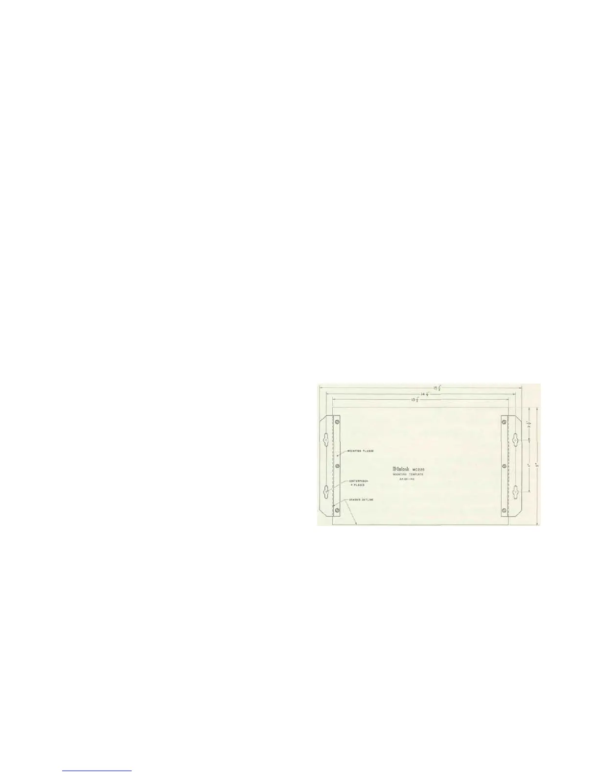
Place the MC225 mounting template on
the area where the amplifier is to be mounted.
Center punch the 4 slotted holes in the
mounting flanges shown on the template.
Remove the template and install four #10
round head screws in the center punch
marks. Do not tighten these screws. Place
the amplifier over the screw heads and slide
the amplifier to either side in the slotted
holes in the mounting flanges. The #10
wood screws can then be tightened securely.
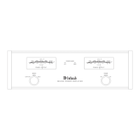
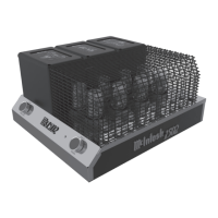
Fig. 4 Bottom of MC225 with mounting flanges attached.
CONNECTING THE MC225
INPUT-STEREO OR TWIN AMPLIFIER
The shielded cable from the left output
of the Mclntosh preamplifier is plugged into
the jack marked INPUT-L. The shielded cable
from the right output of the McIntosh pre-
amplifier is plugged into the jack marked
STEREO INPUT-R. The input switch is moved
to "Stereo."
5
 Loading...