15
All transistors are selected to have nearly constant
current gain over the entire current range they must
cover. Output transistors in particular, have matched
uniform current gain, high current bandwidth prod-
uct and large active region safe operating area. These
Power Transistors are the very latest in semiconduc-
tor technology and incorporate a new design known
as ThermalTrak™. Refer to figure 16. This allows for
the instantaneous and accurate monitor-
ing of the Power Transistor Temperature.
The MC312 Power Output Circuitry has a
specially designed bias circuit to take full
advantage of the ThermalTrak™ Power
Transistors and thus precisely controls
the power amplifier operation over a wide
range of music conditions with the benefits
of lower distortion and cooler operation.
Precision metal film resistors and low dielectric ab-
sorption film capacitors are used in all critical circuit
locations.
may vary considerably
from what a loud-
speaker requires. In the
case of more than one
loudspeaker connected
in parallel, the load to
the power amplifier
may drop to two ohms
or even less. A power
amplifier connected to
a load that is lower than
optimum, causes more
output current to flow,
which results in extra
heat being generated in
the power output stage.
This increase in temperature will result in a reduced
life expectancy for the amplifier.
The Autoformer creates an ideal match between
the power amplifier output stage and the loudspeaker.
The output signals of the amplifier circuit is
coupled together in the unique McIntosh MC312
Output Autoformer. It provides low distortion power
transfer at frequencies from below 20Hz to well
beyond 20,000Hz with optimum impedance points of
two ohms, four ohms and eight ohms. The unequaled
expertise of McIntosh in the design
and manufacturing of autoformers is
legendary in the high fidelity industry.
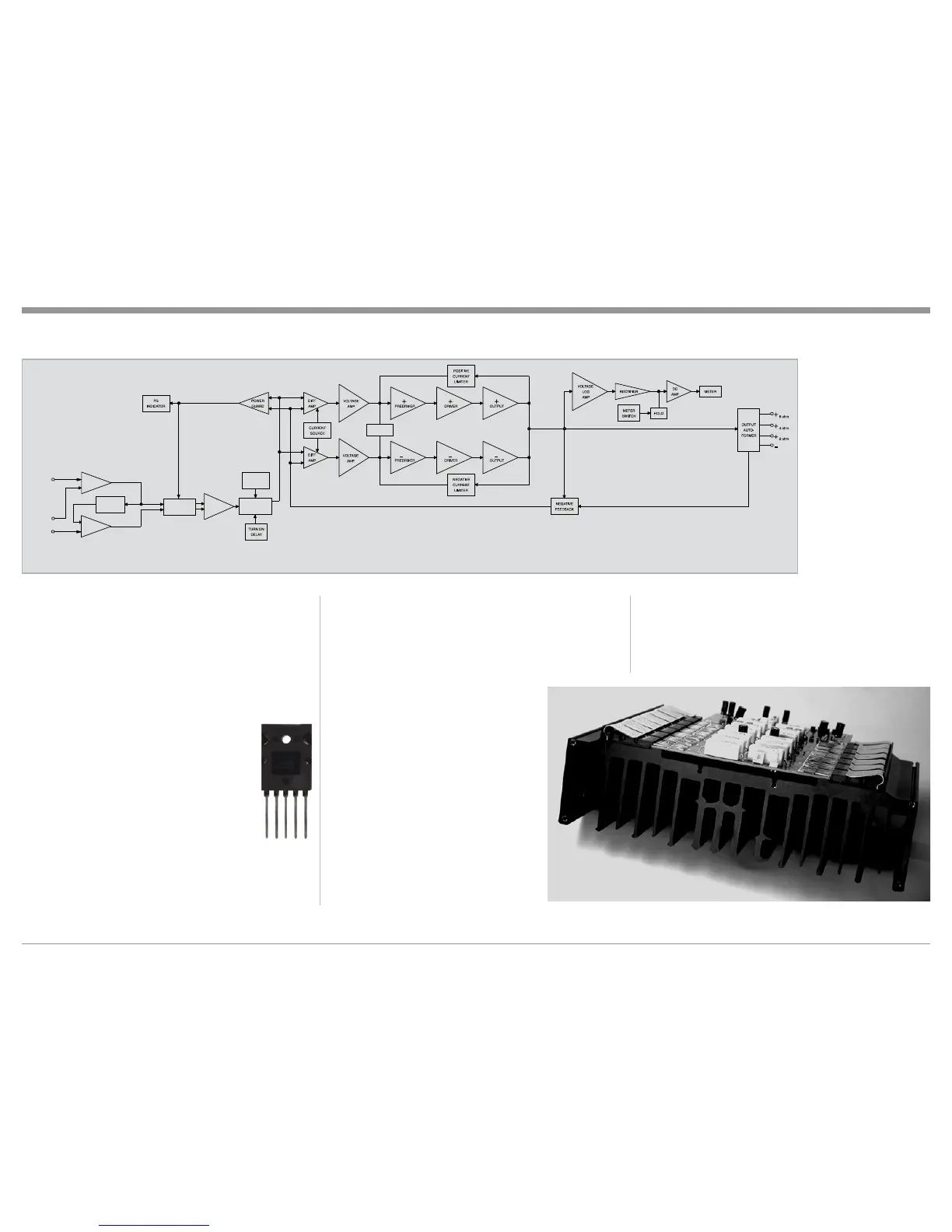
The high efficiency circuit design
of the MC312 contributes to low op-
erating temperatures. More than 1400
square inches of heat sink area keep
the MC312 operating safely with con-
vection cooling. No fans are needed.
Refer to figure 17.
Autoformers
All solid state power amplifier output
circuits work best into what is called
an optimum load. This optimum load
Technical Description
Figure 16
Figure 15
Block Diagram of the Power Amplifier
(one channel shown)
ThermalTrak
DC BIAS
OUTPUT
MUTE
THERMAL
SENSORS
BALANCED
AMP
POWER GUARD
ATTENUATOR
INPUT MODE
SWITCH
-
AMP
+
AMP
UNBALANCED
INPUT
BALANCED
INPUT
+
-
com
Fig ure 17
 Loading...