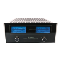
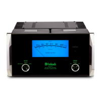
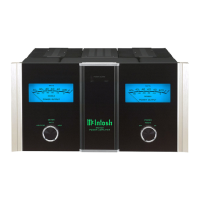
HOW
TO
CONNECT
OUTPUTS
SPEAKER IMPEDANCE
IN OHMS
4 to 8 ohms
8 to 16 ohms
16 ohms and up
BRIDGED MC500 OUTPUT
TERMINAL CONNECTIONS
+4 and -4
+8 and -8
+ 16 and -16
To maintain the MC500 Output signal IN PHASE with the Input signal, connect the
Common or minimum (-) loudspeaker cable to an MC500 Minus (-) L BRIDGED
OUTPUT impedance terminal, and the Hot or (+) cable to an MC500 PLUS (+) R
BRIDGED OUTPUT impedance terminal
IMPORTANT
BE SURE TO REPLACE THE PROTECTIVE POWER OUTPUT TERMINAL COVER
AFTER THE LOUDSPEAKERS ARE CONNECTED. THE MC500 CAN DELIVER
MORE THAN 126 VOLTS FROM THE BRIDGED (MONO) +16 AND -16 TERMINALS,
WHICH CAN BE A SHOCK HAZARD.
HOW TO CONNECT AC POWER
The MC500 is designed to operate on 120 volts 50/60Hz AC current. Power
consumption is rated at 12 amperes UL/CSA. This current requirement applies when the
amplifier is being used for typical music reproduction. The MC500 will draw higher
current with steady test tone signals.
Plug the MC500 into a dedicated AC output with a 15 ampere or higher current
capacity Turn the front panel POWER Switch ON or OFF as needed
POWER CONTROL IN/OUT
The MC500 can be turned ON and OFF remotely by means of a DC POWER
CONTROL signal from a compatible Mclntosh Control Center or Power Amplifier.
Connect a cable from the POWER CONTROL OUT on the accessory Mclntosh unit, to
the POWER CONTROL IN on the MC500. When the accessory unit is turned on, the
Power Control signal will then turn on the MC500. The POWER CONTROL OUT on the
MC500 will feed the same turn on control signal out, time delayed, to an additional
Mclntosh Power Amplifier or compatible accessory.
When a pair of MC500 amplifiers are configured in BRIDGED (Mono) for a stereo
system, connect a cable from the Control Center POWER CONTROL OUT to the
POWER CONTROL IN on one of the MC500 amplifiers. Connect a second cable from
the first MC500 POWER CONTROL IN. Connect the power cord of each MC500 to a
separate dedicated 15 ampere outlet.
A POWER CONTROL cable uses single conductor shielded wire with 1/8 inch
mini phone plugs on each end. Connections are to the sleeve and tip of each plug.
DO NOT PLUG THE MC500 POWER CORD INTO THE BACK PANEL AC OUTLET
OF A PREAMPLIFIER, CONTROL CENTER OR SIMILAR ACCESSORY. PLUG THE
CORD DIRECTLY INTO A WALL SOCKET OR HEAVY DUTY AC POWER STRIP OR
RELAY.
8
 Loading...