8
the Anti-Skate Cord. Refer
to figure 11.
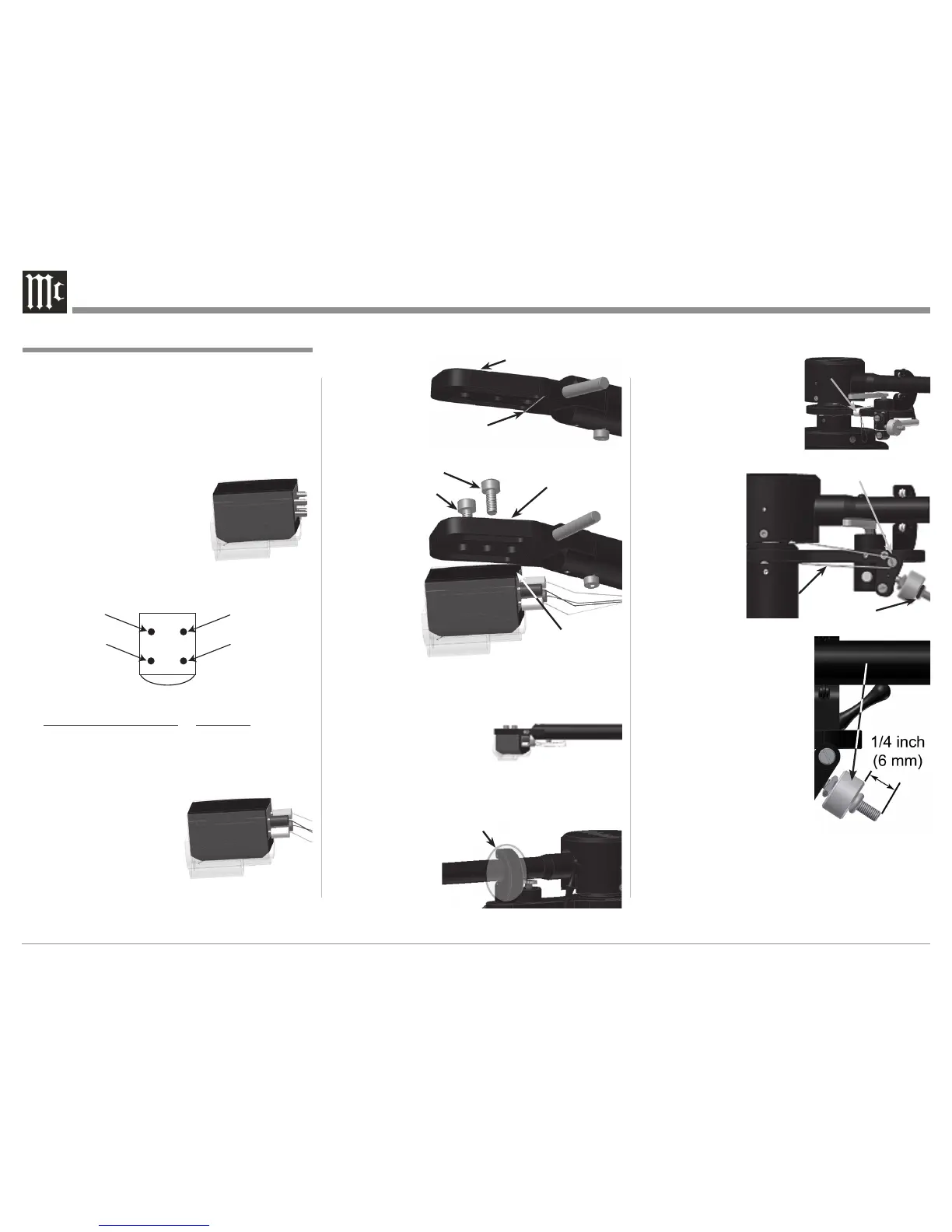
7. Position the Anti-Skate Cord
over the Anti-Skate Pulley.
Refer to figure 12A.
8. Verify the correct setting of
the Anti-Skate for the McIn-
tosh Cartridge by measur-
ing the distance
as indicated in
figure 12B. If
the distance is
not correct, first
slide the “O”
Ring away from
the Anti-Skate
Weight. Rotate
the Anti-Skate
Weight to set the
correct dis-
tance and then slide the “O”
Ring back up the Anti-Skate
Weight.
9. Locate the Tone Arm Counter-
weight. Loosen up the knurled
knob to permit installing the
Counterweight onto the rear
of the Tone Arm. Position the
Counterweight on the Tone
Arm so the front surface of
the Counterweight lines up
with the McIntosh MCC10
Cartridge position marking on
the surface. Refer to figure 13.
Then tighten the knurled knob
to secure the position of the Counterweight.
Locate the McIntosh MCC10 Moving Coil Cartridge,
Tools and Mounting Hardware from the Accessory
Box. In the following steps the Cartridge will be in-
stalled in the Tone Arm Headshell of the Turntable.
CAUTION: To prevent possible damage to the Cartridge
Stylus, DO NOT remove the clear protective
cover at this time.
1. Using an appropriate tool, attach the four color
coded wire lead connec-
tions coming from the front
underside of the Tone Arm
onto the rear of the McIntosh
Moving Coil Cartridge as
follows. Refer to figures 4, 5,
6 and 8.
Cartridge Pin Identification Wire Color
E
R
Green
R Red
E
L
Blue
L White
2. Locate in the Hardware
Package two M2.5 x
4.5mm mounting screws.
3. Position the Cartridge to
the underside of the Tone
Arm Headshell, with
the top rear edge of the
Cartridge parallel to and
touching the machined ridge of the Headshell. Refer to
figures 7 and 8.
4. Insert the two
screws (from
step 2) through
the top of the
headshell and
into the Car-
tridge Body
and fasten them with a small screwdriver. Make sure
the sides of the Cartridge
are parallel to the sides of
the Tone Arm Headshell
before tightening the
screws. Refer to figure 9.
5. Remove any shipping
restraining materials from
the Tone Arm Rest Holder. Refer to figure 10.
6. Remove the foil
tape from the
Tone Arm Sup-
port Arm to free
Assembling the Turntable
Figure 4
Figure 6
Figure 9