11
MT5
CAUTION: To prevent possible damage to the
turntable platter bearing, do not move
the MT5 Precision Turntable with
the platters installed.
In the event a non-supplied Phono Cartridge is to be
installed into the McIntosh MT5 Turntable, please
follow the steps below:
Note: It is recommended that the Professionals at your
McIntosh Dealer, who are skilled in all aspects of
installation and adjustment of the McIntosh MT5
Precision Turntable, perform the assembly, installa-
tion and adjustments.
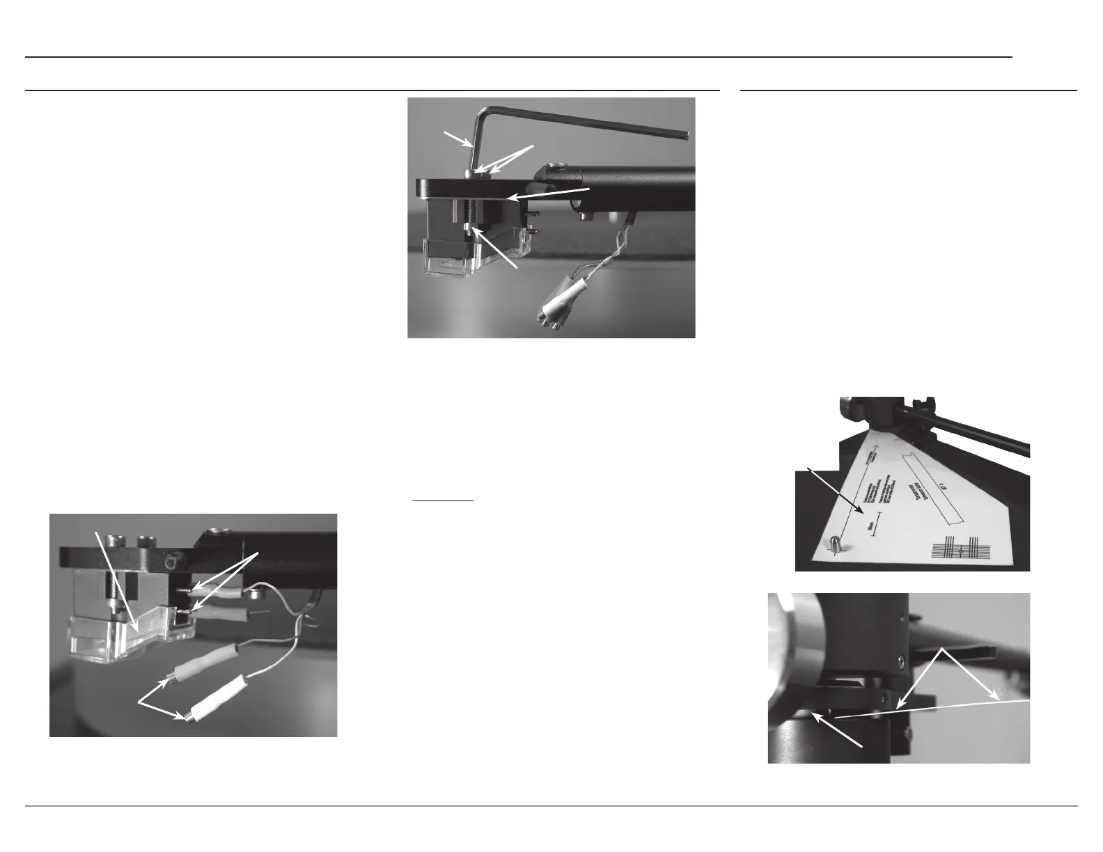
1. Uninstall the factory installed Phono Cartridge
from the MT5 Tone Arm. First, place the Stylus
Guard on the Cartridge. Carefully disconnecting
the four push-on wire clips from the phono
cartridge rear connection pins, using an appropri
-
ate tool. Then remove the mounting screws and
nuts using the supplied allen wrench. Place the
removed cartridge, spacer plate, screws and nuts
in a safe place for possible future use. Refer to
figures 23 and 24.
2. Locate the Hardware Package supplied with the
new cartridge.
3. Using an appropriate tool, attach the four color
coded wire lead connections coming from the
front underside of the Tone Arm onto the rear of
the new Phono Cartridge, following the instruc
-
tions supplied with the Cartridge. Refer to figure
23. Below is the Tone Arm Headshell wire color
lead identification:
Wire Color
Red - Right Channel Positive (+) Signal Connection
Green - Right Channel Negative (-) Ground Connection
White - Left Channel Positive (+) Signal Connection
Blue - Left Channel Negative (-) Ground Connection
4. Position the Cartridge parallel to front and sides
of the headshell and secure it with the supplied
screws and nuts using the appropriate tools.
Refer to figure 24.
5. Proceed to “Tone Arm Adjustments”.
Installing a non-supplied Cartridge Tone Arm Adjustments
Allen
Wrench
Figure 24
Spacer Plate
Screws
Nut
Figure 23
Push-on
wire clips
Connection
pins
Protective
cover
Phono Cartridge/Headshell Alignment
The MT5 Turntable Tone Arm, like all pivoting Tone
Arms, follows a slight arc as it transverses across
the surface of a phonograph record. By adjusting
the distance between the horizontal pivot point of
the Tone Arm and the Stylus Tip, the angular error
across this playback arc is minimized. The Tone Arm
Headshell of the MT5 Turntable allows for making
this adjustment by positioning of the Phono Cartridge
relative to the Headshell. Follow the steps below
using the supplied McIntosh Tone Arm/Cartridge
Alignment Gauge:
1. Place the Gauge over the center spindle post on
the Platter and position the Gauge so the curved
end is in contact with the horizontal pivot of the
Tone Arm. Refer to figures 25 and 26.
Horizontal pivot
Figure 26
Tone Arm/Cartridge
Alignment Gauge
Figure 25
Tone Arm/
Cartridge
Alignment
Gauge