IOMM AGR AGR 055A through 100A 81
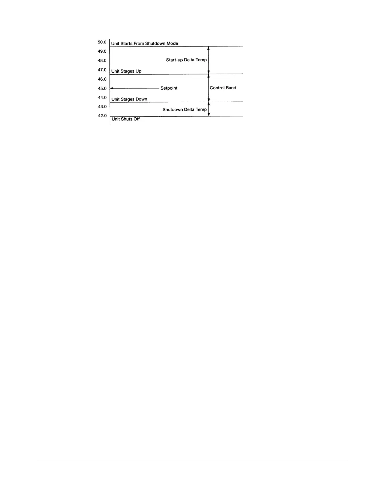
Figure 35, Delta-T Setpoints for Chillers
Menu #15: Softload Set Points—The controller can limit the number of available stages when the
unit is initially started to prevent excessive power consumption and help control overshoot of the
water temperature set point. The maximum number of stages will equal the Soft Load Maximum
Stages for the time period defined in the softload timer set point. If the softload timer is set to zero,
no soft loading will take place. Any time remaining in the softload timer will be displayed when the
soft load option is enabled. During morning start-up, the controller will run the chilled water pump
and sample the loop water temperature for a time equal to the Load Delay set point. If cooling or
heating is required at the end of this time delay, the first compressor will be started.
Menu #16: Compressor Set Points—This menu is used to set the lead-lag order of the refrigerant
circuits. The lead compressor may be manually set to circuit #1 or circuit #2 or the Automatic mode
may be enabled. In Automatic mode, the MicroTech controller will select the refrigerant circuit with
the lowest number starts as the lead. The interstage timer set point sets the delay time between the
current cooling stage and the next stage up request. The stage down request time delay is a fixed
ratio of the stage up delay.
The minimum Start/Start and Stop/Start timers provide protection against compressor short
cycling. During normal operation the Compressor Interstage Timers provide a time delay between
cooling or heating stages.
Menu #17: Head Pressure Set Points—The set points for head pressure control are adjusted from
within this menu. The Minimum Lift Pressure is the minimum differential pressure to be
maintained across the expansion valve. The dead band defines the pressure differential range within
which no fan staging will occur. If the head pressure moves outside of the deadband, the controller
will integrate the pressure error over time. When the Pound/Second exceeds the Stage Up Error or
Stage Down Error set point, the controller will adjust the fan staging up or down to bring the head
pressure back within the deadband. Refer to the section on head pressure control in this manual for
details.
Menu #18: Demand Limit—The Demand Limit set point defines the maximum number of cooling
stages allowed by an external demand limit signal. The actual remote demand limit signal level in
milliamps is also displayed here.
In place of demand limit input, a 0 or 5 volts signal from a unit switch open or cool (5 volts - switch
closed) modes.
Menu #19: Time/Date—The MicroTech controller uses an internal calendar and clock to provide
automatic operation for each day of the year. Provision is made for Manual Override to
accommodate unscheduled building occupancy. Press the Control key to enter the control area of the
menu structure then press the Next Menu key until the display shows Menu Item #24, Set
Date/Time. If the date is incorrect, press the Incr or Decr key and the controller will prompt you for
your password. When you have entered the correct password, the controller will return to the Set
Date/ Time display. Press the Incr or Decr keys to reciprocating the month up or down. Press the
Enter key when the display shows the correct month. The cursor will advance to the Date position
on the display which can be set in the same manner. After pressing the Enter key to set the Date, the
 Loading...


