32 AGZ 035A through 065A IOMM AGZ-3
Operation
Sequence of Operation
Starting
With control power on, 115Vac power is applied through F1 to the compressor crankcase heaters and
control transformer T2. T2 supplies 24Vac to the Global UNT controller. The green light on the
Global UNT controller will begin to flash. The panel Alarm Light will illuminate. Put the System
Switch S1 into the AUTO position. This applies power to the control circuit and a digital input to the
Global UNT controller. Control power is applied through the MHP’s to the compressor inherent
motor protectors. After approximately a two (2) minute time delay, the MP’s are energized and the
panel Alarm Light will turn off. If this is a first start, depress the Freezestat Reset Button for 1
seconds. There is a default time delay of 5 minutes on the Freezestat reset.
Start the chiller water pump and put the chiller into the run mode by closing the remote start / stop
input or time clock input. After the flow switch has made, the Global UNT controller will begin to
ramp up if the chilled water temperature is above the leaving water setpoint dial plus 1/2 the control
band dial. Internal timing functions will vary the stage up time.
The refrigerant circuit starting is switched between circuits every ten (10) starts. This maintains equal
starts on the first compressor of each refrigerant circuit. Refrigerant circuit #1 is assumed as the
starting circuit for the following.
When the first stage of cooling is required, relay BO1 will be energized and if the evaporator pressure
is above the LPSS (low pressure starting setpoint), relay BO7 will be energized starting Compressor
#1 and energizing the liquid line solenoid valve (SV1) through control relay CCR1.
As additional cooling is required, relay BO2 will be energized and if the evaporator pressure is above
the LPSS (low pressure starting setpoint), relay BO8 will be energized starting Compressor #2 and
energizing the liquid line solenoid valve (SV2) through control relay CCR2.
As additional cooling is required, relays BO3 and BO4 will start compressor #3 and #4 respectively.
The reverse will occur as the cooling requirements are reduced. Relays BO4 and BO3 will open
stopping compressors #4 and #3. Relay BO2 will open closing the #2 refrigerant liquid line solenoid
valve. Compressor #2 will continue to operate until the LPLL (low pressure low limit) is reached or
the PDTD (pumpdown delay time period) timer times out. Relay BO8 will open stopping compressor
#2. Relay BO1 will open closing the #1 refrigerant liquid line solenoid valve. Compressor #1 will
continue to operate until the LPLL is reached or the PDTD timer times out. Relay BO7 will open
stopping compressor #1. The compressors will not cycle on if the evaporator pressure exceeds the
LPSS setpoint. The Global Scroll Chiller has a one time pumpdown.
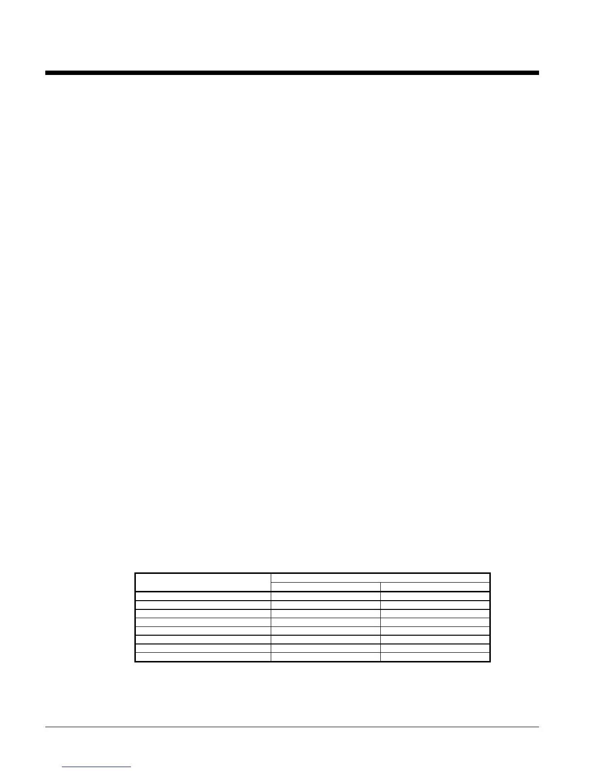
Standard Controller Setpoints (optional Zone Terminal required to
change values)
VALUES
TEMPLATE
NAME
FACTORY SETPOINT RANGE
OA/AI3 Lim SP 80°F 0 to 100°F
OA/AI3 Reset SP -40°F -100 to 100°F
LvgWtr Rband SP 0°F 0 to 15°F
Unoccpd Lvg SP 70°F 40 to 90°F
OA Lockout SP -10°F -20 to 65°F
Lvg Low Lim SP 20°F 20 to 40°F
SoftSta Capcty 50% 0 to 100%
SoftStart Time 2 min 0 to 20 minutes
 Loading...


