38 AGZ 035A through 065A IOMM AGZ-3
Chilled Water Flow Switch
The chilled water flow switch is connected to field wiring terminals #142 and #143 on TB-7. When
the chilled water pump is enabled, the Global UNT controller checks for proof-of-flow through the
flow switch digital input.
Digital Outputs
The digital outputs are controlled by the Global UNT controller. The outputs are double pole double
throw plug-in type relays, with a 24Vac holding coil and 120Vac - 7.0 amp rated contacts. These
relays are field replaceable. Only one contact is used per relay. The contact that is used can be
normally open or normal closed and is dependent on the relay function.
External Alarm Annunciator Circuitry
An audible alarm can be connected to the Alarm Output terminals #19 and #28 of TB-3 of the control
panel and is highly recommended to make certain the operator is alerted to any alarm condition. This
output can also be used to alert a building automation system by paralleling a 24Vac control relay
with the alarm light. This circuit is a 24Vac 1.8 amp maximum load output. The alarm output will be
activated when an alarm condition occurs. Refer to the unit schematic.
Note: The alarm signal is not active during a power failure and will not provide a “Loss of
Power” alarm.
PC Connection
The Global UNT controller can be connected to an IBM or IBM compatible computer for setpoint
changes and downloading of different softwares. A Global UNT Interface Kit is available from your
local McQuay Sales Representative.
Software Identification
Control software is factory installed and tested in each panel prior to shipment. The software is
identified by a program code which is printed on a small label attached to the controller.
Controller Inputs /Outputs
Analog Inputs
Analog inputs are used to read the various temperatures and pressures on the chiller as well as any
customer supplied reset signals. The regulated 5Vdc power supply provides correct operating voltage
for the pressure transducers. This 5Vdc supply cannot be used for other inputs.
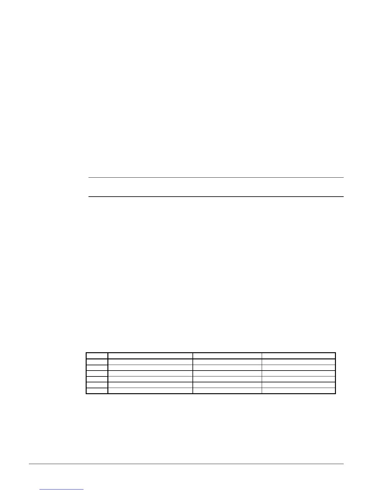
Table 12, Analog Inputs
Input Description Location Range
AI-1 Leaving Chilled Water Temp Leaving Chw nozzle 0 to 120°F(0 - 49°C)
AI-2 Circuit #1 Evap Pressure Circuit #1 Suction Line 0 to 150 psi (0 - 1034kPa)
AI-3 Optional Reset input TB-7 #134 and #135 0/2 to 10VDC / temp sensor
AI-4 Leaving Water Temp Setpoint Dial Control Panel 10 to 60° F ( -12 to 15°C)
AI-5 Circuit #2 Evap Pressure Circuit #2 Suction Line 0 to 150 psi (0 - 1034kPa)
AI-6 Control Band Setpoint Dial Control Panel 0 to 10°F (-17 to -12°C)
 Loading...


