56 AGZ 035A through 065A IOMM AGZ-3
Controller Inputs /Outputs
Analog Inputs
Analog inputs are used to read the various temperatures and pressures on the chiller as well as any
customer supplied 4-20ma reset signals. The controller’s internal regulated 5Vdc and 12Vdc supplies
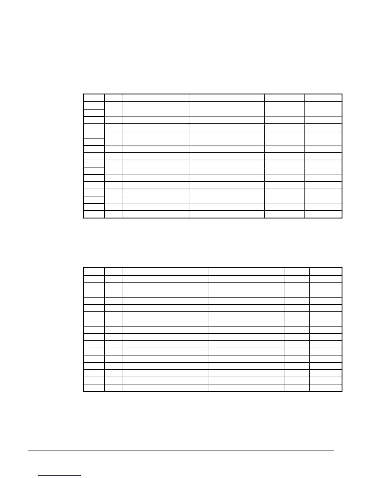
provide correct operating voltage for the sensors. See Table 17 for details.
Table 17, Analog Inputs
Input LED Description Location Range Resolution
0 0 Leaving Chilled Water Temp Leaving Chw nozzle -40 to 263°F 0.1°F
1 1 Circuit #1 Evap Pressure Circuit #1 Suction Line 0 to 145 psi 0.1 psi
2 2 Circuit #2 Evap Pressure Circuit #2 Suction Line 0 to 145 psi 0.1 psi
3 3 Circuit #1 Cond Pressure Compressor Discharge Line- 20 to 450 psi 0.5 psi
4 4 Circuit #2 Cond Pressure Compressor Discharge Line- 20 to 450 psi 0.5 psi
5 5 Voltage Ratio Signal EnGinn Power Supply 4.1 to 5.1 VDC --
6 6 Chw Water Reset Supplied by others 4 to 20 ma DC --
7 7 Demand Limit Signal Supplied by others 4 to 20 ma DC --
8 8 Entering Evap Water Temp Entering Chw Nozzle -40 to 263°F 0.1°F
9 9 Entering Cond Water Temp Enter Cond Water Nozzle -40 to 263°F 0.1°F
10 10 Leaving Cond Water Temp Leaving Cond Water Nozzle -40 to 263°F 0.1°F
11 11 % Total Unit Amps Control Cabinet 0 to 4 VDC --
12 12 Circuit #1 Suction Temp Circuit #1 Suction Line -40 to 263°F 0.1°F
13 13 Circuit #2 Suction Temp Circuit #2 Suction Line -40 to 263°F 0.1°F
14 14 Circuit #1 Liquid Line Temp Circuit #1 Liquid Line -40 to 263°F 0.1°F
15 15 Circuit #2 Liquid Line Temp Circuit #2 Liquid Line -40 to 263°F 0.1°F
Digital Inputs
All Digital Inputs are 24Vac. At 7.5Vac to 24Vac the digital input contacts are considered closed.
Below 7.5Vac, the contracts are considered open. See Table 18 for details and operating
characteristics.
Table 18, Digital Inputs
Input LED Description Circuit Closed Open
0 0 Mechanical High Pressure Switch Circuit #1 Normal Alarm
11
2 2 Motor Protect Switch Compressor Compressor #1 Normal Alarm
33
4 4 Motor Protect Switch Compressor Compressor #3 Normal Alarm
5 5 System Switch Unit Run Stop
6 6 Phase/Voltage Monitor Unit Normal Alarm
7 7 Pumpdown Switch Unit Pmp Dn Normal
8 8 Mechanical High Pressure Switch Circuit #2 Normal Alarm
99
10 10 Motor Protection Switch Compressor #2 Normal Alarm
11 11
12 12 Motor Protection Switch Compressor #4 Normal Alarm
13 13 Chiller Remote Stop Switch Unit Run Stop
14 14 Evap Water Flow Switch Unit Run Stop
15 15 Pumpdown Switch Circuit #2 Pmp Dn Normal
 Loading...


