IM710 27
Binary Outputs-Auxiliary Control Boards
(CCB1 and CCB2)
The optional auxiliary control boards include 9 binary out-
puts that control 9 on-board electromechanical relays. Unit
control devices are wired to these outputs through output ter-
minals on the left side of the board. The functions of these
outputs vary for the different auxiliary board applications.
The following sections describe the output functions for the
auxiliary control board applications.
CCB1 & CCB2
Circuit #1 through Circuit #4 are controlled by the CCB1
and Circuit #5 and #6 are controlled by the CCB2. There are
nine binary output relays on each cooling control board.
These relays are energized based on commands received
from the MCB to provide the appropriate switching actions
in the DX cooling control circuits.
There are a number of different compressor/stage configura-
tions available on these units. The following sections
describe the DX staging sequencing for each configuration.
2-Compressors/2-Stages
There are two equally sized compressors and two indepen-
dent cooling circuits. The unit capacity is increased or
decreased by turning compressors on and off. One of the
compressors is designated the “Lead” and the other “Lag”.
Based on operating hours. The compressor with the fewest
run hours is staged on first and turned off last. When a
capacity increase is required and the cooling capacity is 0%,
the "Lead" compressor is staged on. When further capacity
is required, the "Lag" compressor is staged on. Disabled
compressors are not turned on.
For detailed information regarding compressor lead/lag
operation, refer to the "Compressor Staging" section of the
applicable operation manual (refer to Table 1 on page 3).
Table 15 summarizes the staging sequencing for the 2-Com-
pressor/2-Stage cooling configuration.
Table 15: 2 Compressors / 2 Stages
3-Compressors/3-Stages
There are three equally sized compressors and three indepen-
dent cooling circuits. The unit capacity is increased or
decreased by turning on and off compressors. One of the
compressors is designated the “Lead” and the other “Lag”.
Based on operating hours. When a capacity increase is
required and the cooling capacity is 0%, the "Lead" com-
pressor is staged on. When further capacity is required, a
"Lag" compressor with the least operating hours of the
remaining two is staged on. When further capacity increase
is required, the remaining "Lag" compressor is staged on.
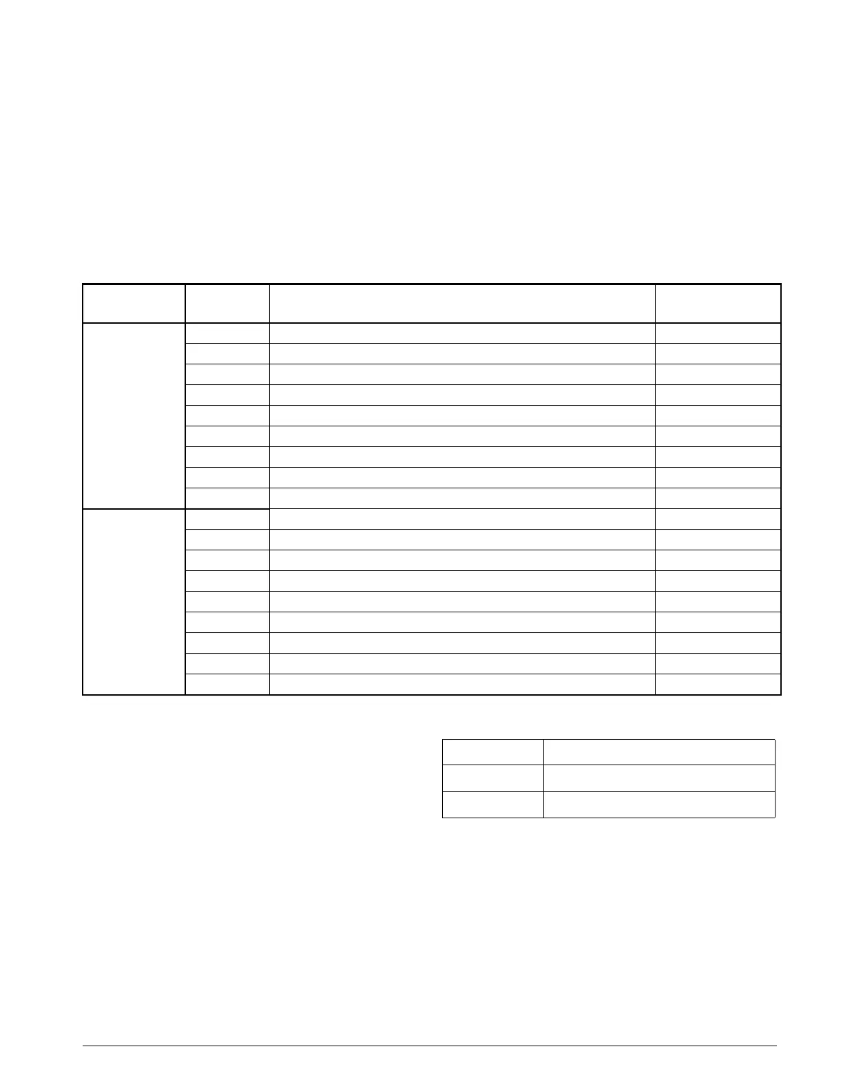
Table 14: Binary Outputs for Cooling Control Boards (CCB1 and CCB2)
Cooling Circuit # Output # Description
Action With Output
On
1
(CCB1)
BO1 Compressor #1 On/Off On
BO2 Compressor #2 On/Off On
BO3 Pump Start On
BO4 Not Used -
BO5 Not Used -
BO6 Compressor #3 On/Off On
BO7 Not Used -
BO8 Not Used -
BO9 Compressor #4 On/Off On
2
(CCB2)
BO1 Compressor #5 On/Off On
BO2 Compressor #6 On/Off On
BO3 Pump Start On
BO4 Not Used -
BO5 Not Used -
BO6 Not Used -
BO7 Not Used -
BO8 Not Used -
BO9 Not Used -
Stages Compressors
11 or 2
21,2
 Loading...


