8 IM 743-1
A. Route the network cable through the third knockout from the left and over to the Modbus
Communication Module.
1. Connect the Modbus Communication Module to the network (see Figure 5 and Figure
6.)
a. Connect one wire of the network cable to Pin 2 of the connector plug.
b. Connect the other wire to Pin 3 of the connector plug.
c. No wire is connected to the remaining pin.
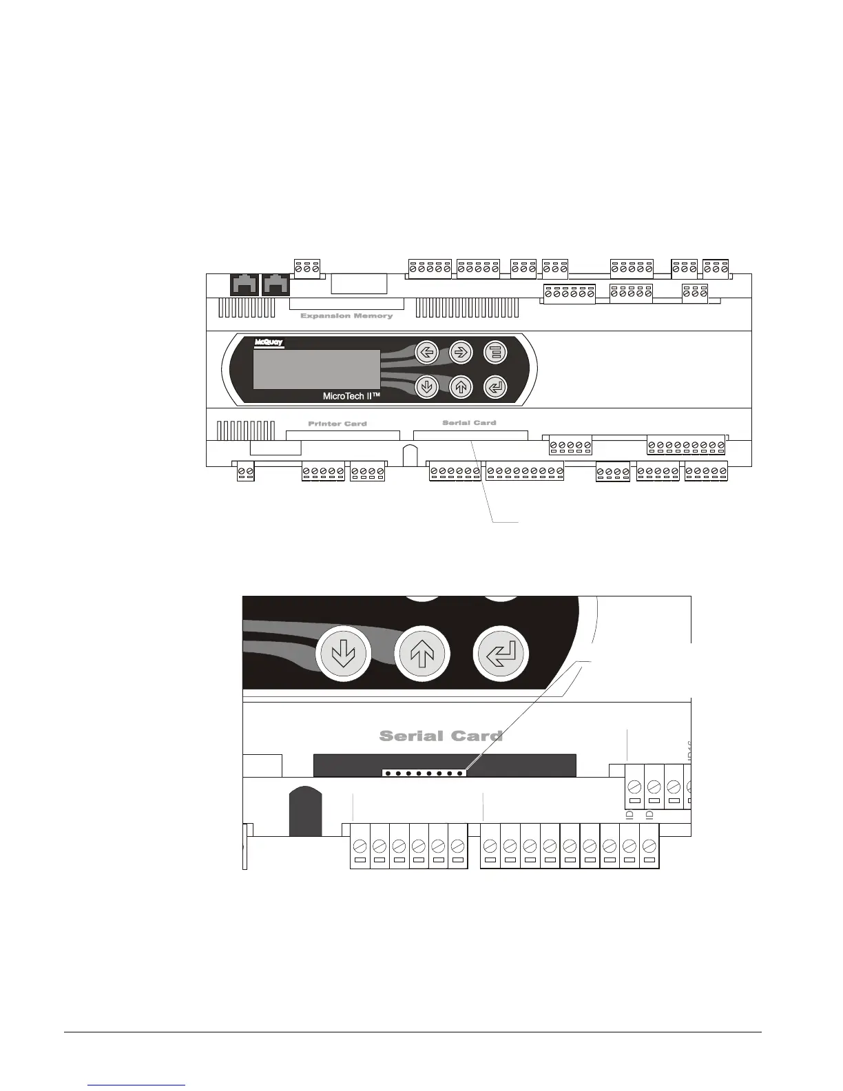
Figure 3. Serial Card Slot Location on Unit Controller
®
Air Conditioni ng
erial
ard
lot
Figure 4. Serial Card Slot Detail
J4
J5
V
G
V
G
0
Y
1
Y
2
Y
3
Y
4
D
1
D
2
D
3
D
4
D
5
D
6
D
7
D
1
5
H
D
1
5
D
C
1
5
J19
8-Pin Connector
for Communication
Module
 Loading...


