Page 10 IM-5WMF(SEER13)-0706
Refrigerant Tubing
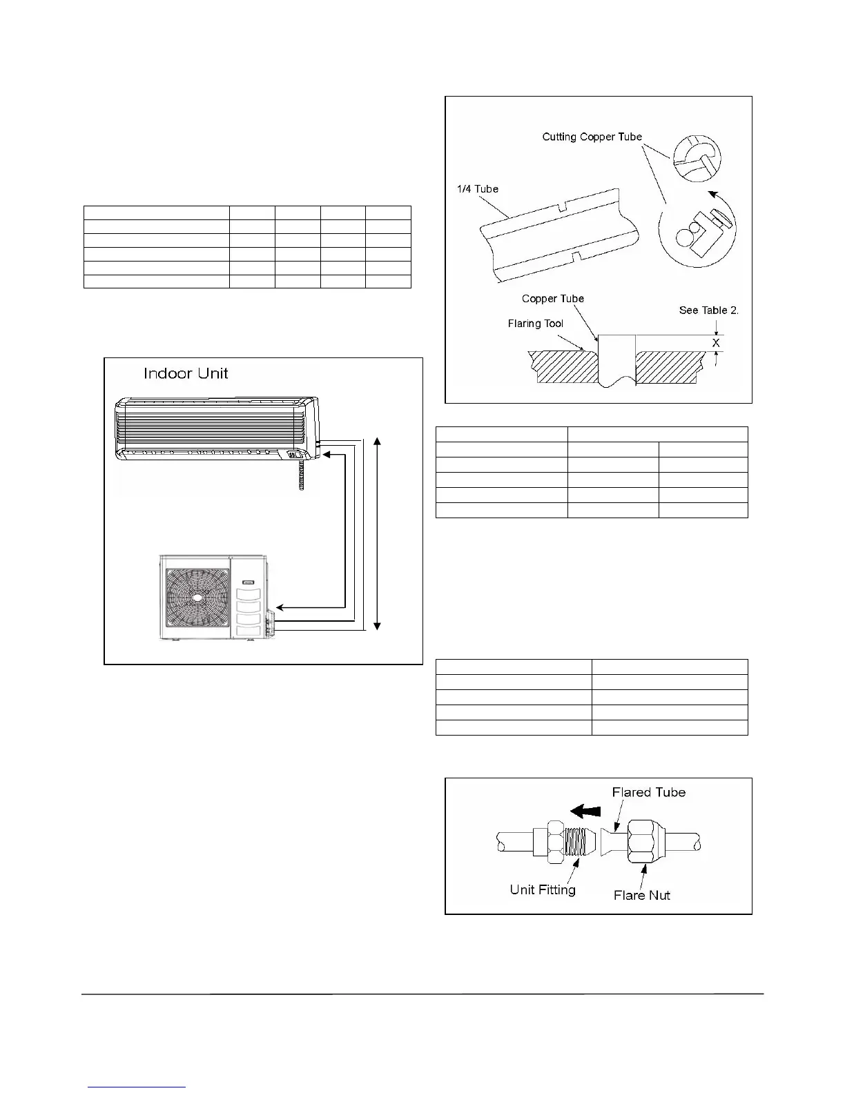
Tubing Length & Elevation
Copper tubing to connect the indoor and outdoor units is
supplied by others or it can be ordered from the factory.
See Table 1 for requirements. Cover both tubes individually
with 3/8” wall foam insulation.
Table 1. Refrigeration Tubing Requirements
Model 10 15 20 25
Maximum length, ft., L
40 40 50 50
Max. elevation, ft., H
16 16 26 26
Max. number of bends
10 10 10 10
Liquid tube size – OD
¼” ¼” ¼” ¼”
Gas tube size - OD
3/8” ½” ½” 5/8”
Note: The refrigerant pre-charged in the outdoor unit is for tubing length up
to 25ft. See Table 5, page 18 for additional R410A refrigerant required on
longer runs.
Figure 10. Tubing Length and Elevation
Tubing Preparation
• Do not use contaminated or damaged copper tubing. Do
not remove plastic, rubber plugs and brass nuts from the
valves, fittings, tubings and coils until you are ready to
connect suction or liquid line into valves or fittings.
• If any brazing work is required, ensure that the nitrogen
gas is passed through coil and joints while the brazing
work is done. This will eliminate soot formation on the
inside wall of the copper tubing.
• Cut the copper tubing with a tube cutter. See Figure 11.
• Remove burrs from cut ends by holding tubing
downwards to prevent metal chips from entering the
tubing.
• Slide the flare nuts, for both the indoor unit and outdoor
unit onto the copper tubing.
• Flare the tubing as shown in Figure 11, Figure 12 and
Table 2.
• The flare must be even and not cracked or scratched.
Figure 11. Cutting and Flaring Tube
Table 2: Tube Flaring Dimensions
Tube Diameter - OD X (in.)
Inch Imperial Rigid
¼ .051 .028
3/8 .063 .039
½ .075 .051
5/8 .087 .067
Tubing Connection To Units
•
Connect the copper tubing to both the indoor and
outdoor units. See Figure 12.
•
Torque each flare nut to specifications. See Table 3.
• Cover both tubes individually with 3/8” minimum wall
foam insulation.
Table: Flare Nut Torque Specifications
Tube Size (in.) Torque (ft./lb.)
¼ 13.3
3/8 31.0
½ 40.6
5/8 48.0
Figure 12. Flare Tubing Connections
H L
Outdoor Unit

 Loading...