Installation Guidelines
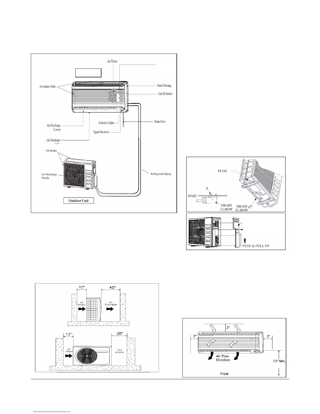
Installation Diagram
Condensate Disposal of Outdoor
Unit (Heat Pump Unit Only)
• There are 2 holes on the base of outdoor unit
for condensed water to flow out. Insert the
drain elbow to one of the holes.
• To install the drain elbow, first insert one
portion of the hook to the base (portion A), then
pull the drain elbow in the direction shown by
the arrow while inserting the other portion to
the base. After installation, check to ensure that
the drain elbow clings to base firmly.
• If the unit is installed where the condensate
may freeze in the base, remove plug at the
bottom of unit for better drainage
• See Figure 2.
Figure 2. Condensate Disposal of Outdoor Unit
(Heat Pump Unit Only)
Installation of the Indoor Unit
Indoor Unit Clearance
The indoor unit must be installed in a manner
to prevent mixing the discharged air with the
return air. Please follow the installation
clearances shown in Figure 3. Do not place the
indoor unit in direct sunlight. The location must
be suitable for piping and drainage, and be
away from doors or windows.
Figure 3. Indoor Unit Minimum Clearances
Installation of Outdoor Unit
Outdoor Unit Clearances
Install the outdoor unit in a manner to prevent mixing hot
discharged air with return air flow. Also the unit should be a
suitable distance from obstructions See Figure 1 for installation
clearances. Double the dimensions shown if surroundings are
more than 72” tall, or if there is an obstruction on top. Select the
coolest possible place where intake air temperature is not greater
than the outside air temperature (maximum 113ºF).
Figure 1. Outdoor Unit Minimum Clearances
IM-5WMF

 Loading...