:$7 (5 ,1/ (7
:+(13 ,3,1*
:$7 (5 287 /(7
&211(&7 25:,7+7,*+ 7)25&(
&$87, 21
%(&$5( )8/12772' $0$*(7+(
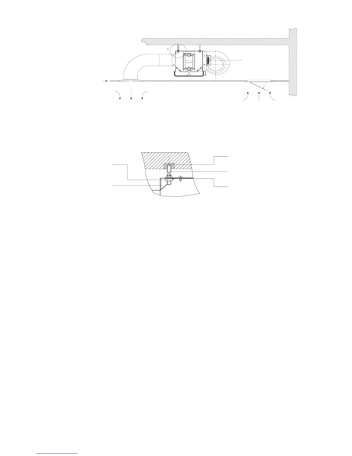
Terminal block
Ceiling access panel
ceiling
Fig. 2
WITH AND WITHOUT PLENUM FORM:
Discharge air
Return air
AIR DUCT CONNECTION
1. Circulatory air pressure drop should be within External Static Pressure
2. Galvanized steel air ducts are suitable.
3. Make sure there is no leak of air.
4. Air duct should e reproof, refer to concerned country national and local regulations.
PIPE CONNECTION
1. Using suitable ttings as water pipe connections. Refer to the specication.
2. The water inlet is on the bottom while outlet on top.
3. The connection must be concealed with rubberized fabric to avoid leakage.
4. Drainpipe can be PVC or steel.
5. The suggested slope of the drainpipe is at least 1:50.
WIRING
1. Wiring connection must be done according to the wiring diagram on the unit.
2. The unit must be GROUNDED well.
3. An appropriate strain relief device must be used to attach the power wires to the terminal box.
4. A 7/8” knockout hole is designed on the terminal box for eld installation of the strain relief device.
5. Field wiring must be complied with the national security regulations.