Do you have a question about the McQuay MicroTech 200 Series and is the answer not in the manual?
Safety and environmental guidelines for installation.
Operating environment specifications for the controller.
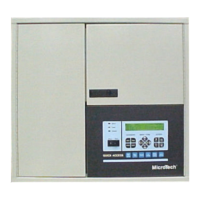
Diagram of major component locations on the control panel.
Core electronic hardware for monitoring and unit control.
Essential steps before initial chiller operation.
Initial power sequence and status LED indicators.
Adjusting screen readability for optimal viewing.
Controls external devices like compressor and fans.
Receives and processes sensor input signals.
Provides variable voltage for field devices.
Primary operator interface for monitoring and control.
Quick access to main menu categories.
Displays unit operating conditions and information.
Accesses and adjusts unit control parameters.
Retrieves current and historical fault data.
Toggles between related status and control items.
Scrolls through menus and specific data items.
Modifies parameters or clears fault conditions.
Protects setpoints and parameters from unauthorized changes.
Direct access to frequently used operational menus.
Navigating menus to view operational data.
Process for modifying unit parameters.
Understanding the format of displayed information.
Displays current unit operating conditions.
Shows evaporator and condenser water temperatures.
Monitors refrigerant states and pressures.
Displays compressor motor current and load.
Monitors oil sump temperature and feed pressure.
Indicates evaporator and condenser pump operation.
Shows cooling tower fan and bypass valve status.
Records compressor and pump run hours.
Monitors master/slave communication status.
Records data at peak load times for analysis.
Sets operational mode: Auto, Manual, Service.
Adjusts chilled water set points and reset parameters.
Configures motor amperage limits and soft load.
Essential for scheduling and proper operation.
Defines daily and weekly operating schedules.
Configures special operating days and times.
Configures start-delay and recirculation timers.
Configures pump selection and lead/lag logic.
Manages cooling tower fan staging based on temp.
Manages cooling tower bypass valve operation.
Sets oil feed and pressure parameters.
Defines alarm thresholds for various parameters.
Configures dual chiller lead/lag control logic.
Settings for manual loading and calibration.
Checks outputs and calibrates transducers.
Configures unit type, network, and sensors.
Shows active and recent alarms with conditions.
Stores previous alarm data for troubleshooting.
Controls alarm relay reporting for warnings, problems, faults.
Allows posting messages via a connected computer.
Configures network hierarchy and communication ports.
Configures lead/lag control between chillers.
Conditions that do not affect immediate chiller operation.
Conditions requiring overrides to keep unit online.