OM 200MICRO 7
With the controller powered up and the green running LED illuminated, the backlite panel on the
display module will be illuminated and the unit status menu will be visible. If the display text looks
faded or appears as “blocks” the contrast control needs to be adjusted. Watch the display and
adjusting the contrast control with a small flat-blade screwdriver until the best setting is determined.
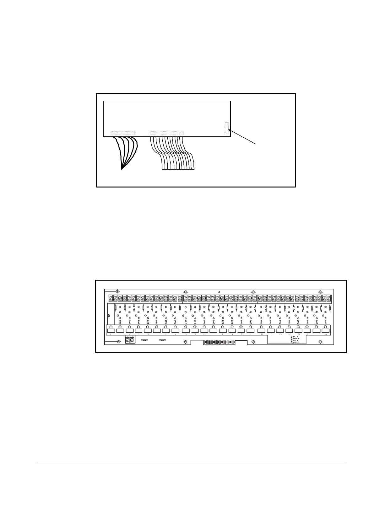
Figure 4, Contrast Adjustment
KDI BOARD
(back side)
Power
Wiring
Ribbon
Cable
Contrast
Adjustment
The MicroTech controller contains factory installed default setpoints which will be appropriate for
most common installations. Step through all of the unit’s setpoints by using the keypad / display and
adjust them as required to meet the specific job requirements. Any faults appearing on the display
should be cleared at this time by pressing the C
LEAR key.
Digital Output Board
The Output Board contains up to 24 solid state relays which are used to control the compressor,
cooling tower fans, solenoid valves and alarm annunciation. It receives control signals from the
Microprocessor Control Board through a 50 conductor ribbon cable.
Figure 5, Digital Output Board
Digital Outputs
Solid state digital relays are used to switch most of the external devices controlled by the MicroTech
panel. These devices may be pumps or solenoids that are either on or off.