8 OM 200MICRO
Table 1, Digital Outputs
No. Description LED Off LED On
0 Alarm LED and Contact Programmable Programmable
1 Unload Solenoid and Front Panel LED - Unload
2 Load Solenoid and Front Panel LED - Load
3 Motor Control Relay Off On
4 Motor Control Relay Latch Unlatched Latched
5 Oil Pump Of f On
6 Oil Sump Heater Off On
7 Oil Cooler close Off On
8 Oil Cooler Open Off On
9 *Hot Gas Bypass Solenoid Off On
10 *Liquid Injection Off On
11 Cooling Tower #1 Off On
12 Cooling Tower #2 Off On
13 Cooling Tower #3 Off On
14 Cooling Tower #4 Off On
15 Evaporator Water Pump #1 Off On
16 Evaporator Water Pump #2 Off On
17 Condenser Water Pump #1 Off On
18 Condenser Water Pump #2 Off On
19 Spare
20 Spare
21 Spare
22 Spare
23 Spare
Analog/Digital Input Board (ADI)
The ADI Board provides low voltage power for the temperature and pressure sensors. It also
provides optical isolation between the Microprocessor Control Board and all 24V switch inputs.
LED's are furnished on the board to give a visual indication of the status of all digital inputs. All
analog and digital signals from sensors, transducers and switches are received by the ADI Board and
then sent to the Microprocessor Control Board for interpretation.
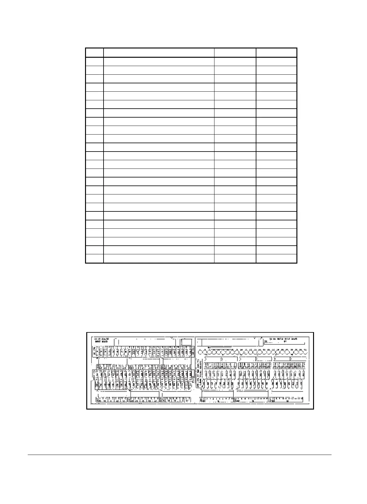
Figure 6, ADI Board
Analog Inputs
Analog inputs arriving at the ADI board are comprised of temperature, pressure, and flow signals. In
addition, the chiller control panel mA receive chilled water reset and demand limit signals in the range