2 McQuay IM 487-4
Introduction
Typical Component Locations
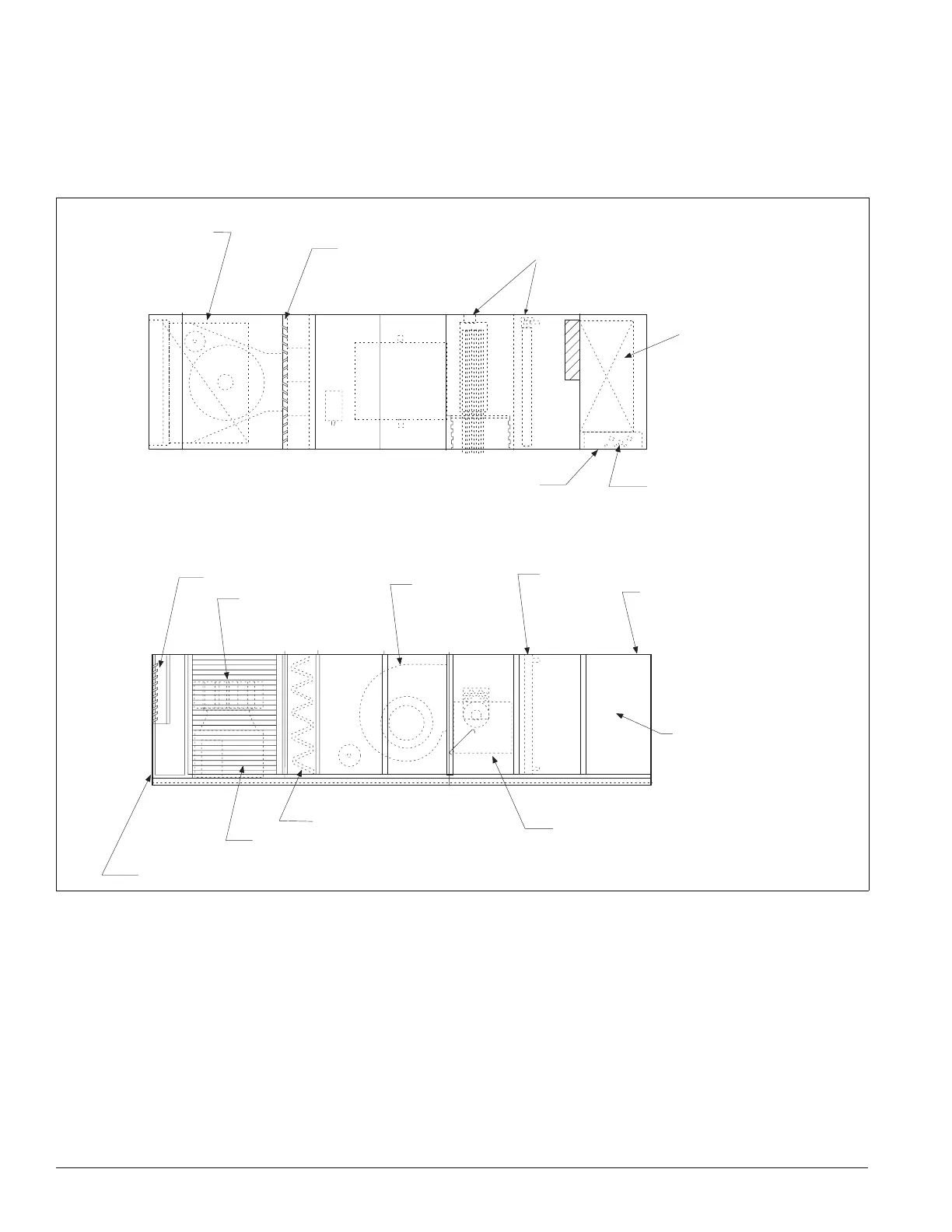
Figure 2 shows a typical blow-through unit with the locations
of the major components. Figure 2 shows a typical
draw-through unit with the locations of the major components.
These figures are for general information only. See the
project’s certified submittals for actual specific dimensions
and locations.
Figure 2. Blow-through configuration (unit size 077C shown)
Bottom return
air opening
Optional outside and
return air dampers
Condensate
drain connections
Bottom discharge
opening
Control entrances
Power entrances
Elevation
Plan View
Optional exhaust dampers
Optional return air fan
Supply air fan
Cooling coil
Discharge plenum
Main control panel
(optional)
Heat section natural gas, steam,
hot water, electric)
Filter section
Optional outside louvers
(both sides)
Optional back return air
Artisan Technology Group - Quality Instrumentation ... Guaranteed | (888) 88-SOURCE | www.artisantg.com

 Loading...


