8
2.4 Circuit Block Diagram
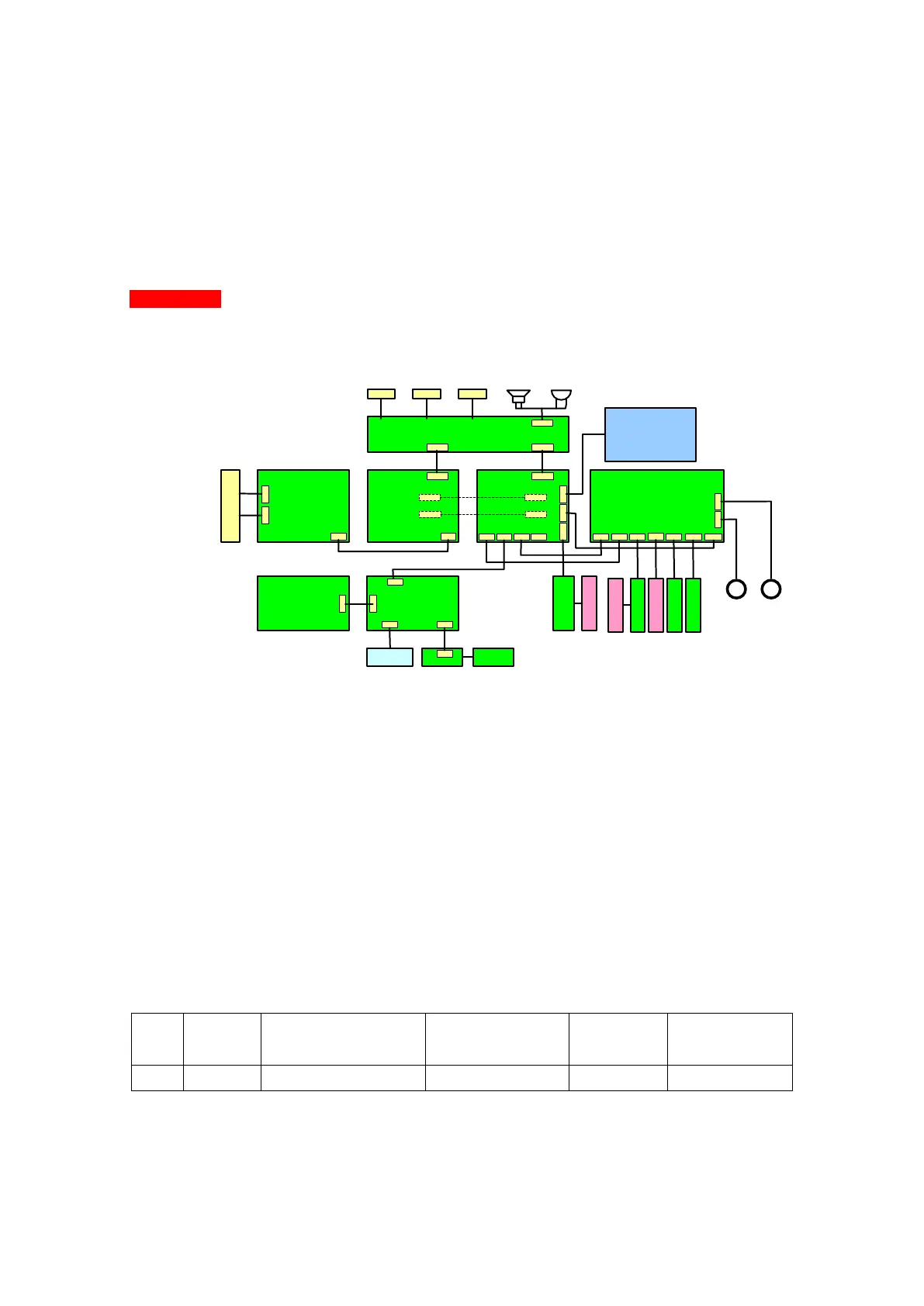
The whole circuit block diagram of SYS-6010 is shown as Figure 6. The parts are as
follows:
AC/DC power board DC/DC power board Power control board
SYS02 board
Alarm
lamp
board
Keyboard
cover
WIFI voice board
Interface board
Alarm/voice horn buzzer
AC
socket
USB1 USB2 RJ11
Pin board
Battery pack
Air-bubble
sensor
Pressure
sensor
Pump tablet
test board
Speed test
board
J4
7PIN
J2
24PIN
J3
8PIN
J9
NA
J10
小3PIN
J2
24PIN
J7
4PIN
J16
3PIN
CON1
8PIN
J5
14PIN
J8
14PIN
CON2
8PIN
CON2
8PIN
CON1
8PIN
J2
14PIN
J8
14PIN
J1
3PIN
J1
3PIN
J2
3PIN
J3
1PIN
J2
4PIN
J1
24PIN
JP1
30PIN
JP1
30PIN
J3
8PIN
J1
24PIN
J6
6PIN
J3
小4PIN
J5
3PIN
J4
4PIN
M
Stepper motor of peristaltic pump
J2
8PIN
Air
bu-
bbl
-e
test
bo-
ard
Auto door
control sensor
M Stepper motor of auto door
J9
4PIN
J7
4PIN
J8
4PIN
J1
7PIN
Pump door
sensor
Lamp
board
V2.0
Figure 6
2.4.1 AC/DC Power Board
a. Circuit Introduction:
The AC/DC power board has adopted the medical level power supply with low
leakage current and high-insulation voltage. It satisfies the requirements of EMC. The
AC/DC power board has an input alternating voltage ranging from 90 to 240V, 50/60Hz,
direct output voltage of 13.6V and the maximum output current of 2A. The AC/DC power
board mainly consists of AC inlet, fuse, EMC filter circuit, rectifier, high voltage DC filter
capacitor, switching tube, pulse width modulator, transformer, rectifier and absorbing
circuit, DC filter circuit, stabilized light decoupling feedback control circuit, etc.
b. Main Testing Point