13
Socket to connect
speaker and buzzer
Connect speaker and buzzer
Socket to connect
power board
Connect CON1 in the power
board
Socket to connect
DC/DC power board
Connect CON2 in the DC/DC
power board
2.4.6 Interface Socket
a. Socket Introduction
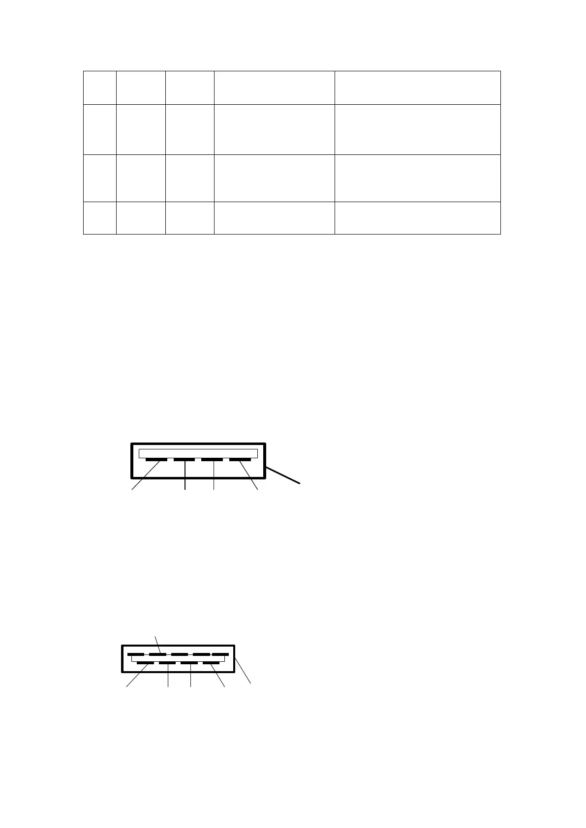
(1)USB1 socket (BUS1): USB2.0 socket interface. To connect the external DC power
supply, bar code scanner of RS485 serial port, power supply of the intravenous
workstation with RS485 correspondence, drop sensor signal, program update of SYS02
board CPU. The external power supply should be used with the matched cables. The DC
input power is 9-15V and the current is 1A.
The definition of socket signal
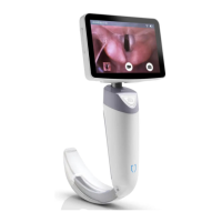
(2)USB2 socket (BUS2): USB3.0 socket interface. To connect the external DC power
supply, bar code scanner of RS485 serial port, drop sensor signal, nurse call, and
program update of SYS02 board CPU. The external power supply should be used with the
matched cables. The DC input power is 9-15V and the current is 1A.
The Definition of Socket Signal
Remark: When the voltage of external power supply connecting to the USB1 and USB2
socket is over 13.6V, the external battery in SYS-6010 can be fully charged. If the voltage