15
© 05.2022
5.21
M
E
D
E
N
U
S
G
a
s
-
D
r
u
c
k
r
e
g
e
l
g
e
r
t
M
E
D
E
N
U
S
G
a
s
-
D
r
u
c
k
r
e
g
e
l
g
e
r
t
7.4 Initial Commissioning / Recommissioning
Initial commissioning of the system components shall be carried out by the operator. For commissioning, please refer to
thedocumentslistedunderitem1“GeneralInformation”andthesystemoperator'sworkinstruction.
The devices delivered by MEDENUS Gas-Druckregeltechnik GmbH are factory-set to the operating data specified by the
customer.ThisdataislistedontheAcceptanceTestCertificate“ATC”(availableasanoption)andthetypeplate.
Prior to commissioning of the system, a functional test must be performed on the gas pressure
regulator (GPR), if applicable, and the safety shut-off and safety relief valves.
Procedure
• Close the ball valve upstream of the valves and fittings (item 5.01).
• Close the downstream shut-off devices (item 5.13) (ball valve, solenoid or pneumatic valve).
• Depressurize the system (item 5.11).
• Close the venting ball valve (item 5.11).
• Slowly open ball valve upstream of the valves and fittings (item 5.01).
If the inlet shut-off device is equipped with a bypass, the latter must be slowly opened for pressure
compensation as step 1. This is followed by slowly opening the inlet shut-off valve which will close the
bypass. The same is true of the outlet shut-off valve.
• For the functional test of the GPR, let gas flow via the discharge line (venting)
(item 5.11) to the outside atmosphere and read the set regulating pressure on
the outlet pressure gauge (item 5.12).
• It may be necessary to correct the setpoint of the outlet pressure.
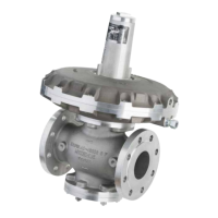
This is done by turning the GPR setpoint setting screw (item 5.22) to the right
or left, in order to increase and decrease the setpoint, respectively, after
removal of the GPR sealing cap (item 5.21).
• After closing the discharge line (item 5.11), a constant closing pressure within
the closing pressure class can be read on the outlet pressure gauge (item
5.12).
• Slowly open the shut-off valve (item 5.13), close the discharge line (item 5.11)
and read the set regulating pressure on the outlet pressure gauge (item 5.12).
• It may be necessary to correct the setpoint of the outlet pressure once again.
• Screw on the sealing cap (item 5.15) of the safety shut-off valve (SSV) again.
• Screw on the GPR sealing cap (item 5.21) again.
Changing the control range
Switching to the control range of a different setpoint spring can be done for the GPR
while the device is pressurized.
• Take off the sealing cap (item 5.21) and unscrew the setting screw (item 5.22),
• Pull out the spring (item 5.25) and replace the spring with one that fits.
• Screw in the setting screw (item 5.22) again.
• Set the desired setpoint and screw on the sealing cap (item 5.21).
Note
Note
 Loading...