FITTING OF ACCESSORIES AND DETACHABLE PARTS
BLADE REPLACEMENT
1 Pull vacuum hose complete with hose/cowelling connector from the vacuum cowelling.
2 Pull vacuum cowelling from saw unit body.
3 Unscrew blade clamp retaining screw with nutwrench provided and remove retaining
screw, spring washer and blade clamp.
4 Replace or index blade as required, ensuring it is seated properly on the square drive
shaft. If not, discard, or resulting damage or ineciency of the saw could result.
5 Ret blade clamp, spring washer and retaining screw. Note ! It is imperative the spring
washer is in place or the blade may loosen whilst in use.
6 Firmly retighten clamp retaining screw with nutwrench provided. Note ! use of the
nutwrench alone will clamp the blade suciently, additional leverage is not necessary as
this could result in damage to the internal mechanism.
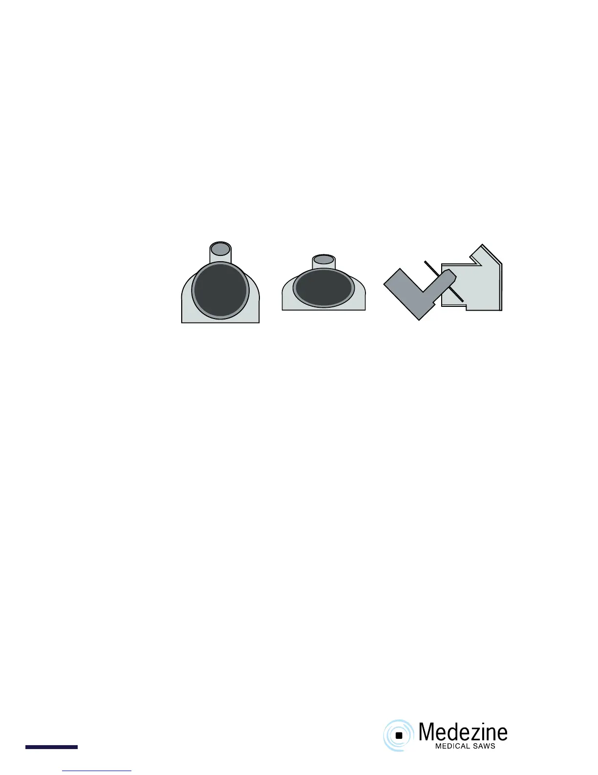
7 Ret vacuum cowelling. This will pass over a 64mm blade if compressed to an oval shape
and tted as shown.
8 Ret hose/cowelling connector, complete with hose, to cowelling.
HOSE REPLACEMENT.
1 Remove hose/cowelling connector from cowelling. Remove connector from vacuum
hose by pulling and screwing (clockwise) simultaneously. Remove vacuum hosing from
hose/ltration unit connector similarly.
2 Ret vacuum hosing to hose/cowelling connector by pushing and screwing (clockwise)
simultaneously until fully engaged. Ret vacuum hosing to hose/ltration unit
connector similarly.
3 Ret hose/cowelling connector, complete with hose, to vacuum cowelling.
PAPER FILTER REPLACEMENT USING NEGATIVE PRESSURE FEATURE.
1 Ensure saw unit is in its cradle. (park position).
2 Switch system on from the saw unit.
3 While the system is running, release the two toggle clamps and remove the top cover.
4 The paper lter and support ange can now be removed without loss of contents.
Note ! The cloth lter is not removed.
5 The paper lter can now be sealed and disposed of in the appropriate manner. Please
refer to your Safety Ocer.
6 Switch system o from the saw unit.
7 Insert new paper lter ensuring it is ‘expanded’ to ll the cloth lter. ‘Neck’ the top of the
paper lter so that the support ange may be tted over the ‘necked’ portion. Fan out
edge of paper lter over the support ange. Ensure that entry to the paper lter is not
restricted.
8 Ret top cover and reax toggle clamps.
REPLACEMENT OF CLOTH FILTER AND HIGH EFFICIENCY CARTRIDGE FILTER WILL BE
FOUND IN PREVENTIVE MAINTENANCE SECTION PAGE 9.
Normal
Fitting