Slit Lamp Microscope USER MANUAL
16 / 29
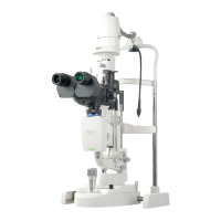
3. Take out the slit lamp part (Fig.2.1.1), put
it on the rails of the metal plate, check
whether the wheels can move steadily on
the rails. (Fig.2.2.2), place the rail cover
to the rail, remove four screws attached to
the rail with the screw driver, retighten
the previously removed screws.(Fig.2.2.2
and 2.2.3)
4. Take out the binocular tubes of
microscope part (Fig.2.1.3), match the
groove on the binocular tubes with the pin
on the microscope body. Fasten the fixing
screw on the body to the microscope
(Fig.2.2.4). ATTENATION:Don’t touch
the objective lens and eyepiece when
assembling.
Fig.2.2.4
5. Place the gas shield directly on the gas
shield screw (Fig.2.2.5)
Fig.2.2.5
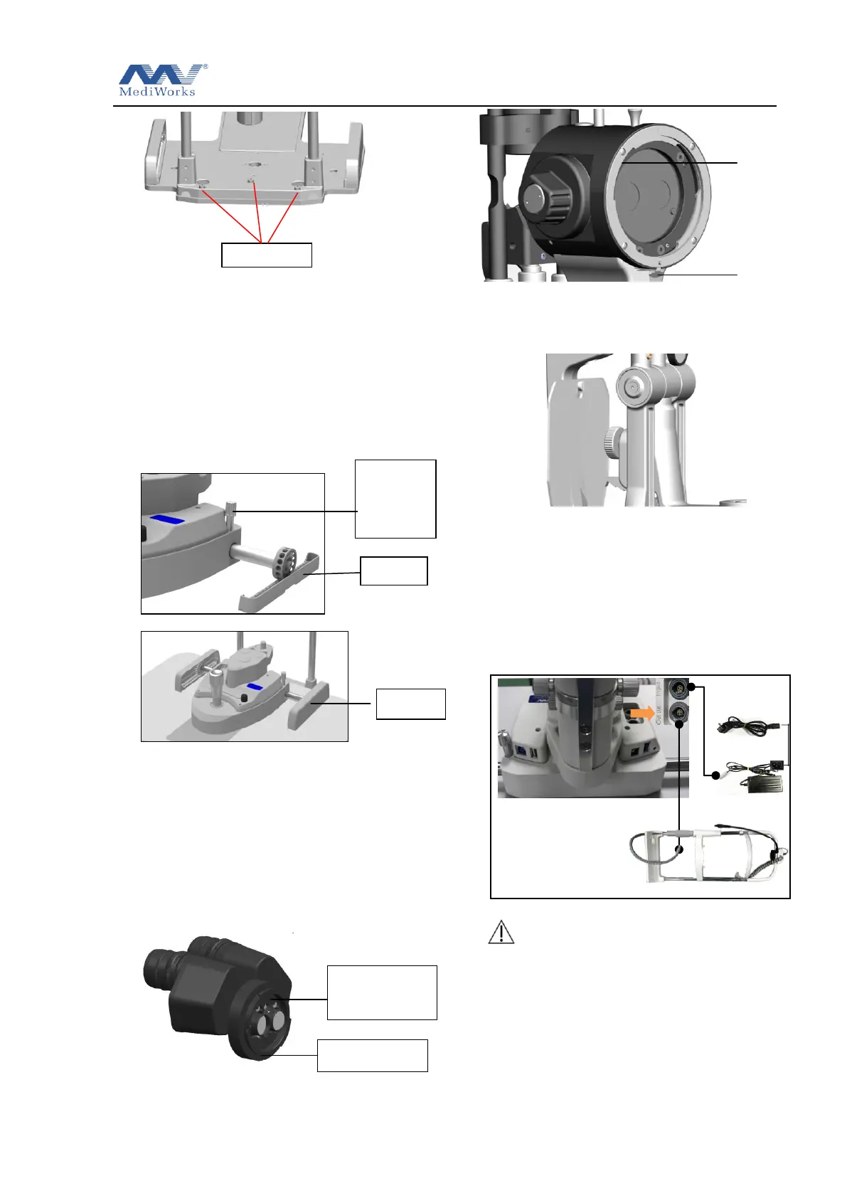
6. Refer to Figure 2.2.6. The 4-pin aviation
plug of the chin-rest is connected to the
―Output‖ on the base of the slit lamp
microscope; the power adapter is
connected to the ―Input‖ on the base of
the slit lamp microscope.
Note: The limited slot on the air
socket should be aligned
corresponded slot when
plugging and unplugging. Do
not force the plug.
7. The power supply can work normally