8
MDS86845 Series (PIC-00311)
Revised: 12/28/2018
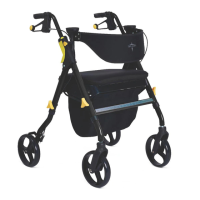
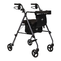
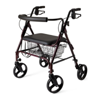
Brake Handle Assembly
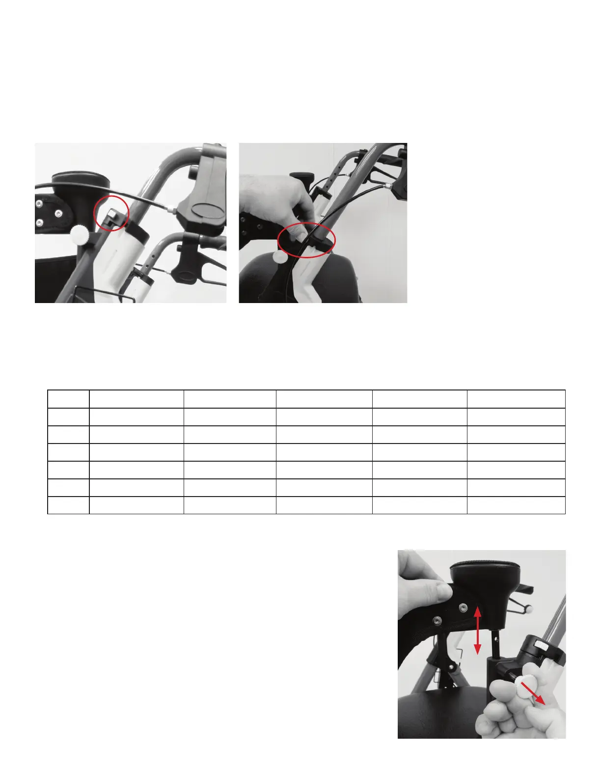
1. Press and hold the yellow button in (item C in Figure 1 above and Figure 9 below).
2. Insert hand grip into appropriate hole (see Figure 10).
Note: Keep brake cable to the outside of the walker.
3. Repeat steps 1-2 for other hand grip.
Legs
Hole 1 Hole 2 Hole 3 Hole 4 Hole 5
Hole 1
39" (99.1 cm) 38" (96.5 cm) 37" (94 cm) 36" (91.4 cm) 35" (88.9 cm)
Hole 2 38.25" (97.2 cm) 37.25" (94.6 cm) 36.25" (92.1 cm) 35.25" (89.5 cm) 34.25" (87 cm)
Hole 3 37.5" (95.3 cm) 36.5" (92.7 cm) 35.5" (90.2 cm) 34.5" (87.6 cm) 33.5" (85.1 cm)
Hole 4 36.75" (93.3 cm) 35.75" (90.8 cm) 34.75" (88.3 cm) 33.75" (85.7 cm) 32.75" (83.2 cm)
Hole 5 36" (91.4 cm) 35" (88.9 cm) 34" (86.4 cm) 33" (83.8 cm) 32" (81.3 cm)
Hole 6 35.25" (89.5 cm) 34.25" (87 cm) 33.25" (84.5 cm) 32.25" (81.9 cm) 31.25" (79.4 cm)
Arms
Note: 1 is the highest, 5 is the shortest setting.
Handle Height adjustments (set to Dimension B above):
Figure 9 Figure 10
Adjust the backrest height for comfort:
1. Pull the Backrest Height Adjust Lock (item G in Figure 1 above).
Raise or lower the backrest to desired height.
2. Release the Backrest Height Adjustment Knob. Move backrest
to desired height. Place knob firmly into appropriate hole.
Ensure backrest is firmly locked in place.
3. Repeat steps 1-2 for the other side.
Chart 2
 Loading...