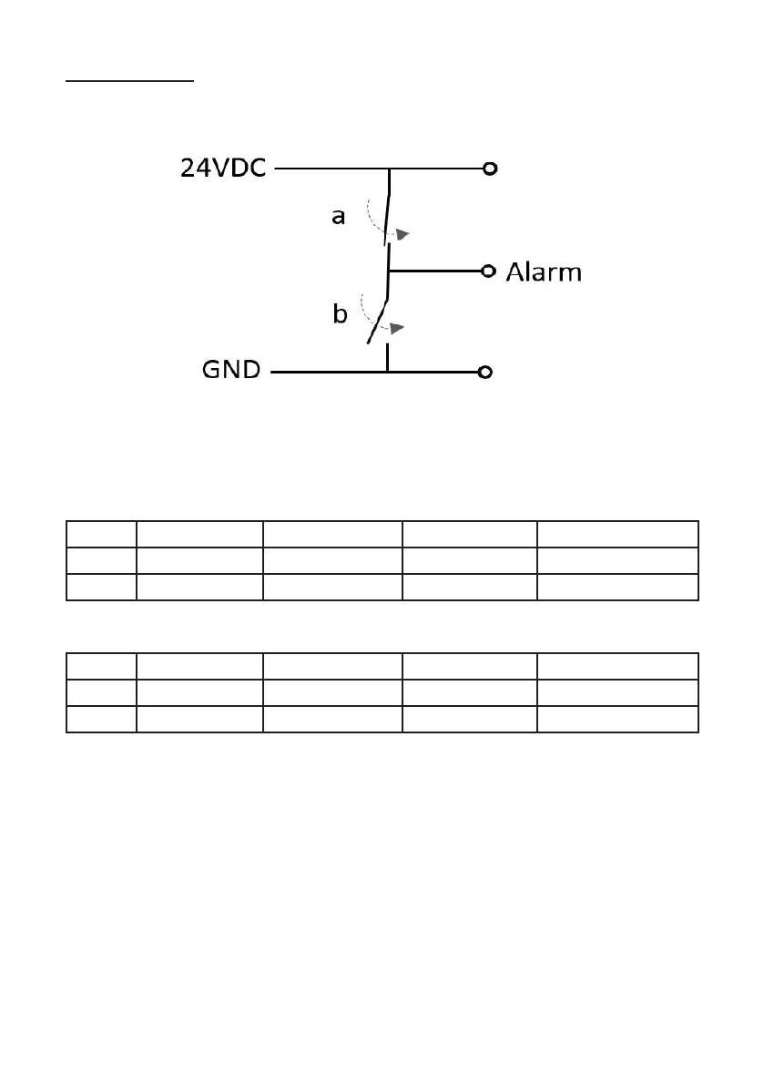
Option 2 - PNP
Transistor-driven switch which presents a pull-down resistor to GND on the alarm pin.
This conguration is the same for both alarm pins (pin-2 and pin-4).
Simplied Diagram of NPN output
Logic Table
Alarm True = Hi
Start State Solid Green Flashing Red Solid Red
White Hi Lo Hi Hi
Black Hi Lo Lo Hi
Alarm True = Lo
Start State Solid Green Flashing Red Solid Red
White Hi Hi Lo Lo
Black Hi Hi Hi Lo
Note: On unit power-ip, both alarm pins remain in Hi state for up to 60 seconds before
these are used as alarm pins.
16
Note: When ‘a’ is closed, ‘b’ is
open and vicaversa.